Jeep Grand Cherokee WJ. Manual - part 10


  Index      Jeep     Jeep Grand Cherokee WJ - service repair manual 2001 year


Search            


Content   ..  8  9  10  11   ..


Jeep Grand Cherokee WJ. Manual - part 10


HUB/BEARING

DESCRIPTION

The bearing used on the front hub of this vehicle is

the combined hub and bearing unit type assembly.
This unit assembly combines the front wheel mount-
ing hub (flange) and the front wheel bearing into a
one piece unit. The wheel mounting studs are the
only

replaceable

component

of

the

hub/bearing

assembly.

OPERATION

The hub/bearing assembly is mounted to the steer-

ing knuckle and is retained by three mounting bolts
accessible from the back of the steering knuckle. The
hub/bearing unit is not serviceable and must be
replaced as an assembly if the bearing or the hub is
determined to be defective.

DIAGNOSIS AND TESTING

SUSPENSION AND STEERING SYSTEM
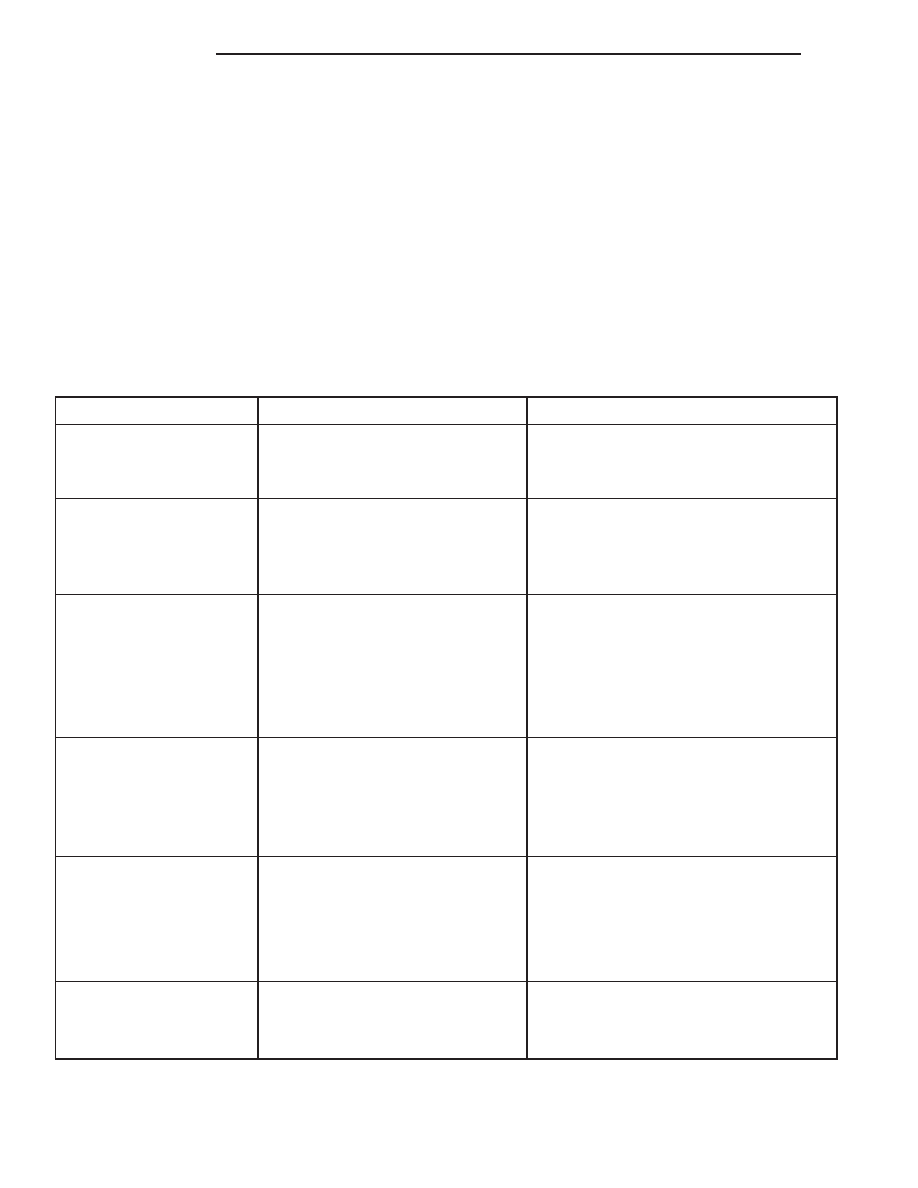
CONDITION

POSSIBLE CAUSES

CORRECTION

FRONT END NOISE

1. Loose or worn wheel bearings.

1. Adjust or replace wheel bearings.

2. Loose or worn steering or
suspension components.

2. Tighten or replace components as
necessary.

EXCESSIVE PLAY IN
STEERING

1. Loose or worn wheel bearings.

1. Adjust or replace wheel bearings.

2. Loose or worn steering or
suspension components.

2. Tighten or replace components as
necessary.

3. Loose or worn steering gear.

3. Adjust or replace steering gear.

FRONT WHEELS SHIMMY

1. Loose or worn wheel bearings.

1. Adjust or replace wheel bearings.

2. Loose or worn steering or
suspension components.

2. Tighten or replace components as
necessary.

3. Tires worn or out of balance.

3. Replace or balance tires.

4. Alignment.

4. Align vehicle to specifications.

5. Leaking steering dampener.

5. Replace steering dampener.

VEHICLE INSTABILITY

1. Loose or worn wheel bearings.

1. Adjust or replace wheel bearings.

2. Loose or worn steering or
suspension components.

2. Tighten or replace components as
necessary.

3. Tire pressure.

3. Adjust tire pressure.

4. Alignment.

4. Align vehicle to specifications.

EXCESSIVE STEERING
EFFORT

1. Loose or worn steering gear.

1. Adjust or replace steering gear.

2. Power steering fluid low.

2. Add fluid and repair leak.

3. Column coupler binding.

3. Replace coupler.

4. Tire pressure.

4. Adjust tire pressure.

5. Alignment.

5. Align vehicle to specifications.

VEHICLE PULLS TO ONE
SIDE DURING BRAKING

1. Uneven tire pressure.

1. Adjust tire pressure.

2. Worn brake components.

2. Repair brakes as necessary.

3. Air in brake line.

3. Repair as necessary.

2 - 8

SUSPENSION

WJ

DESCRIPTION AND OPERATION (Continued)

CONDITION

POSSIBLE CAUSES

CORRECTION

VEHICLE LEADS OR
DRIFTS FROM STRAIGHT
AHEAD DIRECTION ON
UNCROWNED ROAD

1. Radial tire lead.

1. Cross front tires.

2. Brakes dragging.

2. Repair brake as necessary.

3. Weak or broken spring.

3. Replace spring.

4. Uneven tire pressure.

4. Adjust tire pressure.

5. Wheel Alignment.

5. Align vehicle.

6. Loose or worn steering or
suspension components.

6. Repair as necessary.

7. Cross caster out of spec.

7. Align vehicle.

KNOCKING, RATTLING
OR SQUEAKING

1. Worn shock bushings.

1. Replace shock.

2. Loose, worn or bent steering/
suspension components.

2. Inspect, tighten or replace components
as necessary.

3. Shock valve.

3. Replace shock.

IMPROPER TRACKING

1. Loose, worn or bent track bar.

1. Inspect, tighten or replace component as
necessary.

2. Loose, worn or bent steering/
suspension components.

2. Inspect, tighten or replace components
as necessary.

SERVICE PROCEDURES

SERVICE WARNINGS AND CAUTIONS

CAUTION: Suspension

components

with

rubber

bushings must be tightened with the vehicle at nor-
mal ride height. It is important to have the springs
supporting the weight of the vehicle when the fas-
teners are torqued. If springs are not at their normal
ride position, vehicle ride comfort will be affected
and cause premature bushing wear.

REMOVAL AND INSTALLATION

SHOCK ABSORBER

REMOVAL

(1) Remove the nut, retainer and grommet from

the shock stud in the engine compartment (Fig. 2).

(2) Raise and support the front axle.
(3) Remove the lower mounting nuts from the axle

bracket (Fig. 3). Remove the shock absorber.

INSTALLATION

(1) Position the lower retainer and grommet on the

shock stud. Insert the shock absorber through the
shock tower hole.

(2) Install the lower shock studs into the axle

bracket.

(3) Install the mounting nuts and tighten to 28

N·m (250 in. lbs.).

(4) Remove support and lower the vehicle.
(5) Install the upper grommet, retainer and nut on

the stud in the engine compartment. Hold the shock
stud with a 8 mm wrench and tighten the nut to 35
N·m (26 ft. lbs.).

Fig. 2 Upper Shock Mounting

1 – RETAINER
2 – STUD
3 – NUT
4 – GROMMET

WJ

SUSPENSION

2 - 9

DIAGNOSIS AND TESTING (Continued)

COIL SPRINGS

REMOVAL

(1) Raise and support the vehicle. Position a

hydraulic jack under the axle to support it.

(2) Remove the wheel and tire assemblies.
(3) Remove stabilizer bar links mounting nuts and

bolts from the axle brackets.

(4) Remove shock absorbers lower mounting nuts

from the axle brackets.

(5) Remove the track bar mounting bolt from the

axle bracket.

(6) Lower the axle until the spring is free from the

upper mount and isolator (Fig. 4).

(7) Remove the spring from the vehicle.
(8) Remove and inspect the upper and lower

spring isolators.

INSTALLATION

(1) Install the upper isolator.
(2) Install the lower isolator with the isolator loca-

tor nub in the axle pad hole (Fig. 5).

(3) Position the coil spring on the axle spring pad.

CAUTION: Ensure the spring is positioned on the
lower isolator with the end of the spring coil
against the isolator spring locator (Fig. 6).

(4) Raise the axle and guide the springs onto the

spring upper mounts and lower shock studs into the
axle brackets.

(5) Install the shock absorbers lower mounting

nuts.

(6) Install the stabilizer bar link to the axle

bracket and install the mounting bolts and nuts.

(7) Install the track bar to the axle bracket and

install the mounting bolt.

NOTE: It may be necessary to pry the axle assem-
bly over to install the track bar bolt.

(8) Tighten all suspension components to proper

torque.

(9) Install the wheel and tire assemblies.
(10) Remove support and lower vehicle.

Fig. 3 Lower Shock Mounting

1 – SHOCK ABSORBER
2 – MOUNTING NUTS

Fig. 4 Front Coil Spring

1 – UPPER ISOLATOR
2 – COIL SPRING
3 – LOWER ISOLATOR
4 – STABILIZER LINK

Fig. 5 Lower Isolator

1 – LOCATING NUB
2 – LOWER ISOLATOR
3 – AXLE SPRING PAD
4 – LOCATING HOLE

2 - 10

SUSPENSION

WJ

REMOVAL AND INSTALLATION (Continued)

STEERING KNUCKLE

For service procedures on the steering knuckle and

ball joints refer to Group 3 Differentials And Driv-
eline.

LOWER SUSPENSION ARM

REMOVAL

(1) Raise the vehicle and support the front axle.
(2) Remove the lower suspension arm nut and bolt

from the axle bracket (Fig. 7).

(3) Remove the nut and bolt from the frame rail

bracket and remove the lower suspension arm (Fig.
7).

INSTALLATION

(1) Position the lower suspension arm in the axle

bracket and frame rail bracket.

NOTE: The end of the arm with the oval bushing
attaches to the axle bracket.

(2) Install the axle bracket bolt and nut finger

tight.

(3) Install the frame rail bracket bolt and nut fin-

ger tight.

(4) Remove support and lower the vehicle.
(5) With the vehicle on the ground tighten the

frame bracket bolt to 156 N·m (115 ft. lbs.). Tighten
the axle bracket nut to 163 N·m (120 ft. lbs.).

(6) Check

the

alignment

if

new

parts

were

installed.

UPPER SUSPENSION ARM

REMOVAL

(1) Raise vehicle and support the axle.
(2) Remove the upper suspension arm mounting

nut and bolt (Fig. 8) from the axle bracket.

(3) Remove the nut and bolt (Fig. 8) at the frame

rail and remove the upper suspension arm.

INSTALLATION

(1) Position the upper suspension arm at the axle

and frame rail.

(2) Install the bolts and finger tighten the nuts.
(3) Remove the supports and lower the vehicle.

Fig. 6 Isolator Spring Locator

1 – COIL SPRING
2 – SPRING LOCATOR
3 – LOWER ISOLATOR

Fig. 7 Lower Suspension Arm

1 – LOWER SUSPENSION ARM
2 – FRAME RAIL BRACKET
3 – AXLE BRACKET

Fig. 8 Upper Suspension Arm

1 – UPPER SUSPENSION ARM
2 – FRAME BOLT
3 – AXLE BOLT

WJ

SUSPENSION

2 - 11

REMOVAL AND INSTALLATION (Continued)


Content   ..  8  9  10  11   ..