Jeep Grand Cherokee WJ. Manual - part 9


  Index      Jeep     Jeep Grand Cherokee WJ - service repair manual 2001 year


Search            


Content   ..  7  8  9  10   ..


Jeep Grand Cherokee WJ. Manual - part 9


CONDITION

POSSIBLE CAUSES

CORRECTION

KNOCKING, RATTLING
OR SQUEAKING

1. Worn shock bushings.

1. Replace shock.

2. Loose, worn or bent steering/
suspension components.

2. Inspect, tighten or replace components
as necessary.

3. Shock valve.

3. Replace shock.

IMPROPER TRACKING

1. Loose, worn or bent track bar.

1. Inspect, tighten or replace component as
necessary.

2. Loose, worn or bent steering/
suspension components.

2. Inspect, tighten or replace components
as necessary.

SERVICE PROCEDURES

PRE-ALIGNMENT

Before starting wheel alignment, the following

inspection and necessary corrections must be com-
pleted. Refer to Suspension and Steering System
Diagnosis Chart for additional information.

(1) Inspect tires for size and tread wear.
(2) Set tire air pressure.
(3) Inspect front wheel bearings for wear.
(4) Inspect front wheels for excessive radial or lat-

eral runout and balance.

(5) Inspect ball studs, linkage pivot points and

steering gear for looseness, roughness or binding.

(6) Inspect suspension components for wear and

noise.

(7) Road test the vehicle.

WHEEL ALIGNMENT

Before each alignment reading the vehicle should

be jounced (rear first, then front). Grasp each
bumper at the center and jounce the vehicle up and
down three times. Always release the bumper in the
down position.

To obtain an accurate alignment, a 4 wheel align-

ment machine must be used and the equipment cali-
bration verified.

CAMBER

The wheel camber angle is preset. This angle is not

adjustable and cannot be altered.

CASTER

The wheel caster angle is preset. This angle is not

adjustable and cannot be altered.

TOE POSITION

NOTE: For an accurate wheel toe position adjust-
ment the engine must be engine running.

(1) Apply parking brakes.

(2) Start the engine and turn wheels both ways

before straightening the steering wheel. Center and
secure the steering wheel.

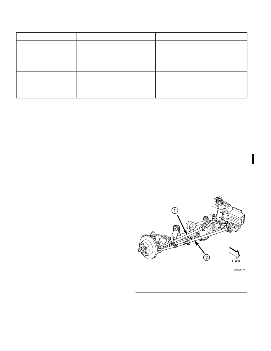
(3) Loosen the tie rod adjustment sleeve clamp

bolts (Fig. 2).

(4) Turn the sleeve to obtain the preferred positive

TOE-IN specification. Position the clamp bolts as
shown (Fig. 2) for proper clearance.

(5) Tighten the clamp bolts to 68 N·m (50 ft. lbs.).

Tighten bolts with E-coated clamp and yellow tag to
41 N·m (30 ft. lbs.).

NOTE: Make sure the toe setting does not change
during clamp tightening.

(6) Verify alignment specifications, then turn the

engine off.

STEERING WHEEL CENTERING

NOTE: The steering wheel can be centered without
affecting the toe position.

(1) Loosen the drag link adjustment sleeve clamp

bolts.

Fig. 2 Steering Linkage

1 – DRAG LINK ADJUSTMENT SLEEVE
2 – TIE ROD ADJUSTMENT SLEEVE

2 - 4

SUSPENSION

WJ

DIAGNOSIS AND TESTING (Continued)

2000 Jeep Grand Cherokee
Publication No. 81-370-0047
TSB 26-10-99

October, 1999

(2) Turn the adjustment sleeve to center the

wheel.

(3) Position the clamp bolts as shown (Fig. 2) for

proper clearance.

(4) Tighten the clamp bolts to 68 N·m (50 ft. lbs.).

Tighten bolts with E-coated clamp and yellow tag to
41 N·m (30 ft. lbs.)

(5) Road test the vehicle to verify the wheel is cen-

tered.

SPECIFICATIONS

ALIGNMENT

NOTE: Specifications are in degrees.

FRONT WHEELS - STANDARD SUSPENSION

ANGLE

PREFERRED

RANGE

MAX. RT to LT Difference

CASTER

+6.75°

+6.0° to +7.5°

0.5°

CAMBER

−0.37°

−0.75° to 0°

0.5°

TOTAL TOE

+0.20°

NA

0.05°

FRONT WHEELS - UP-COUNTRY SUSPENSION

REAR AXLE

ANGLE

PREFERRED

RANGE

MAX. RT

to LT

Difference

CASTER

+6.5°

+5.7° to

+7.2°

0.5°

CAMBER

−0.37°

−0.75°

to 0°

0.5°

TOTAL TOE

+0.20°

NA

0.05°

ANGLE

RANGE

CASTER

0° to −0.5

THRUST ANGLE

6

0.25°

TOTAL TOE-IN

0° to +0.5°

WJ

SUSPENSION

2 - 5

SERVICE PROCEDURES (Continued)

2000 Jeep Grand Cherokee
Publication No. 81-370-0047
TSB 26-10-99

October, 1999

FRONT SUSPENSION

TABLE OF CONTENTS

page

page

DESCRIPTION AND OPERATION

FRONT SUSPENSION . . . . . . . . . . . . . . . . . . . . . . 6
COIL SPRINGS AND ISOLATORS . . . . . . . . . . . . . 7
JOUNCE BUMPER. . . . . . . . . . . . . . . . . . . . . . . . . 7
LOWER SUSPENSION ARMS AND BUSHINGS . . . 7
SHOCK ABSORBERS . . . . . . . . . . . . . . . . . . . . . . 7
STABILIZER BAR . . . . . . . . . . . . . . . . . . . . . . . . . . 7
STEERING KNUCKLE . . . . . . . . . . . . . . . . . . . . . . 7
TRACK BAR. . . . . . . . . . . . . . . . . . . . . . . . . . . . . . 7
UPPER SUSPENSION ARMS AND BUSHINGS . . . 7
HUB/BEARING . . . . . . . . . . . . . . . . . . . . . . . . . . . . 8

DIAGNOSIS AND TESTING

SUSPENSION AND STEERING SYSTEM . . . . . . . . 8

SERVICE PROCEDURES

SERVICE WARNINGS AND CAUTIONS . . . . . . . . . 9

REMOVAL AND INSTALLATION

SHOCK ABSORBER. . . . . . . . . . . . . . . . . . . . . . . . 9
COIL SPRINGS . . . . . . . . . . . . . . . . . . . . . . . . . . 10
LOWER SUSPENSION ARM. . . . . . . . . . . . . . . . . 11
STEERING KNUCKLE . . . . . . . . . . . . . . . . . . . . . 11
UPPER SUSPENSION ARM . . . . . . . . . . . . . . . . . 11
FRONT AXLE BUSHING. . . . . . . . . . . . . . . . . . . . 12
TRACK BAR. . . . . . . . . . . . . . . . . . . . . . . . . . . . . 12
STABILIZER BAR . . . . . . . . . . . . . . . . . . . . . . . . . 12
HUB BEARING. . . . . . . . . . . . . . . . . . . . . . . . . . . 13
WHEEL MOUNTING STUDS. . . . . . . . . . . . . . . . . 14

SPECIFICATIONS

TORQUE CHART . . . . . . . . . . . . . . . . . . . . . . . . . 14

SPECIAL TOOLS

FRONT SUSPENSION . . . . . . . . . . . . . . . . . . . . . 15

DESCRIPTION AND OPERATION

FRONT SUSPENSION

The front suspension (Fig. 1) is a link/coil design

comprised of :

• Drive axle

• Shock absorbers

• Coil springs

• Upper and lower suspension arms

• Stabilizer bar

• Track bar

• Jounce bumpers

CAUTION: Components attached with a nut and
cotter pin must be torqued to specification. Then if
the slot in the nut does not line up with the cotter
pin hole, tighten nut until it is aligned. Never loosen
the nut to align the cotter pin hole.

CAUTION: Suspension

components

with

rubber

bushings must be tightened with the vehicle at nor-
mal ride height. It is important to have the springs
supporting the weight of the vehicle when the fas-
teners are torqued. If springs are not at their normal
ride position, vehicle ride comfort will be affected
and cause premature bushing wear.

Fig. 1 Front Suspension

1 – SHOCK
2 – COIL SPRING
3 – UPPER SUSPENSION ARM
4 – STABILIZER BAR
5 – LOWER SUSPENSION ARM
6 – TRACK BAR

2 - 6

SUSPENSION

WJ

SHOCK ABSORBERS

DESCRIPTION

The top of the shock absorbers are bolted to the

body. The bottom of the shocks are bolted to the axle
brackets. The standard shocks have conventional
twin tube construction and are low pressure gas
charged. Gas charging prevents cavitation during
rough road operation. Up-Country shocks are mono
tube design and are high pressure gas charged.

OPERATION

The shock absorbers dampen jounce and rebound

motion of the vehicle over various road conditions
and limit suspension rebound travel.

JOUNCE BUMPER

DESCRIPTION

They are mounted under the unibody rails to min-

imize transmission of noise to the passenger com-
partment.

OPERATION

The jounce bumpers are used to limit suspension

travel in compression.

COIL SPRINGS AND ISOLATORS

DESCRIPTION

The coil springs mount up in the wheelhouse which

is part of the unitized body bracket. A rubber dough-
nut isolator is located between the top of the spring
and the body. The bottom of the spring seats on a
axle isolator made of rubber with a steel insert.

OPERATION

The coil springs control ride quality and maintain

proper ride height. The isolators provide road noise
isolation.

STEERING KNUCKLE

DESCRIPTION

The knuckle is a single casting with legs machined

for the upper and lower ball joints. The knuckle also
has machined mounting locations for the front brake
calipers and hub bearing.

OPERATION

The steering knuckle pivot between the upper and

lower ball joint. Steering linkage attached to the
knuckle allows the vehicle to be steered.

LOWER SUSPENSION ARMS AND BUSHINGS

DESCRIPTION

The lower suspension arms are hydroformed steel

and use voided oval bushings at one end of the arm.

OPERATION

The bushings provide isolation from the axle. The

arms mount to the unibody frame rail bracket and
the axle brackets. The arm and bushings provide
location and react to loads from the axle.

UPPER SUSPENSION ARMS AND BUSHINGS

DESCRIPTION

The upper suspension arms are hydroformed steel

and use rubber bushings at each end of the arm.

OPERATION

The arms mount to the unibody frame rail bracket

and the axle brackets. The arm and bushings provide
location and react to loads from the axle. The bush-
ings provide isolation from the axle.

STABILIZER BAR

DESCRIPTION

The bar extends across the front underside of the

chassis and is mounted to the frame rails. Links are
connected from the bar to the axle brackets. The sta-
bilizer bar and links are isolated by rubber bushings.

OPERATION

The stabilizer bar is used to control vehicle body

roll during turns. The spring steel bar helps to con-
trol the vehicle body in relationship to the suspen-
sion.

TRACK BAR

DESCRIPTION

The bar is attached to a frame rail bracket and

axle bracket. The bar is forged and has non replace-
able isolator bushings at both ends.

OPERATION

The track bar is used to control front axle lateral

movement and provides cross car location of the axle
assembly.

WJ

SUSPENSION

2 - 7

DESCRIPTION AND OPERATION (Continued)


Content   ..  7  8  9  10   ..