Infiniti QX56 (JA60). Manual - part 986


  Index      Infiniti     Infiniti QX56 (JA60) - service repair manual 2010 year


Search            


Content   ..  984  985  986  987   ..


Infiniti QX56 (JA60). Manual - part 986


TM-246

< DISASSEMBLY AND ASSEMBLY >

ASSEMBLY

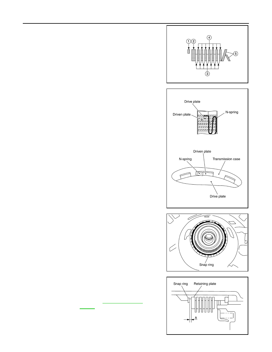
Take care with order of plates.

• Snap ring (1)

• Retaining plate (2)

• Drive plate (3)

• Driven plate (4)

• Dish plate (5)

• Driveplate/Driven plate: 7/7

19. Assemble N-spring.
20. Install reverse brake retaining plate in transmission case.

21. Install snap ring in transmission case.

22. Measure clearance (A) between retaining plate and snap ring. If

not within specified clearance, select proper retaining plate.

WCIA0625E

SCIA5249E

SCIA2439E

Clearance “A”

: 0.7 - 1.1mm (0.028 - 0.043 in)

Retaining plate

: Refer to 

TM-266, "Reverse 

Brake"

.

SCIA3129E

ASSEMBLY

TM-247

< DISASSEMBLY AND ASSEMBLY >

C

E

F

G

H

I

J

K

L

M

A

B

TM

N

O

P

23. Install needle bearing to transmission case.

CAUTION:

• Take care with the direction of needle bearing. Refer to

TM-201, "Location of Adjusting Shims, Needle Bearings,

Thrust Washers and Snap Rings"

.

• Apply petroleum jelly to needle bearing.

24. Install output speed sensor (1) to transmission case and tighten

bolt (

) to specified torque.

CAUTION:

• Do not subject sensor to impact by dropping or hitting it.

• Do not disassemble sensor.

• Do not allow metal filings or any foreign material to get on

the sensor's front edge magnetic area.

• Do not place sensor in an area affected by magnetism.

25. Install new rear oil seal until it is flush into the rear extension

case (2WD models) using Tool or adapter case (4WD models)

using suitable tool.

CAUTION:

• Apply ATF to rear oil seal.

• Do not reuse rear oil seal.

26. Install return spring (1) to parking pawl (2).

SCIA5031E

Output speed sensor bolt : 5.8 N·m (0.59 kg-m, 51 in-lb)

JSDIA1321ZZ

Tool number

: ST33400001 (J-26082)

WCIA0475E

SCIA6180J

TM-248

< DISASSEMBLY AND ASSEMBLY >

ASSEMBLY

27. Install parking pawl (with return spring) and pawl shaft to rear

extension (2WD models) or adapter case (4WD models).

28. Install parking actuator support to rear extension (2WD models)

or adapter case (4WD models).

29. Install needle bearing (1) to rear extension (2WD models) or

adapter case (4WD models).

CAUTION:

Apply petroleum jelly to needle bearing.

30. Install seal rings to output shaft.

CAUTION:

• Do not reuse seal rings.

• Apply petroleum jelly to seal rings.

31. Install parking gear to output shaft.

SCIA3424E

SCIA3423E

SCIA6179J

SCIA5209E

SCIA5247E

ASSEMBLY

TM-249

< DISASSEMBLY AND ASSEMBLY >

C

E

F

G

H

I

J

K

L

M

A

B

TM

N

O

P

32. Install output shaft in transmission case.

CAUTION:

Do not mistake front of shaft for rear because both sides

look similar (thinner end is front side).

33. Install bearing race to output shaft.

34. Install rear extension assembly (2WD models) or adapter case assembly (4WD models) according to the

following procedures. 

a. 2WD models
i.

Apply recommended sealant (Genuine Anaerobic Liquid Gasket

or equivalent. Refer to 

GI-15, "Recommended Chemical Prod-

ucts and Sealants"

.) to rear extension assembly as shown.

CAUTION:

Completely remove all moisture, oil, old sealant and any

foreign material from the transmission case and rear exten-

sion assembly mating surfaces.

ii.

Install rear extension assembly to transmission case.

CAUTION:

Insert the tip of parking rod between the parking pawl and

the parking actuator support when assembling the rear

extension assembly.

SCIA5030E

SCIA5245E

SCIA5212E

SCIA5029E


Content   ..  984  985  986  987   ..