Infiniti QX56 (JA60). Manual - part 972


  Index      Infiniti     Infiniti QX56 (JA60) - service repair manual 2010 year


Search            


Content   ..  970  971  972  973   ..


Infiniti QX56 (JA60). Manual - part 972


TM-190

< REMOVAL AND INSTALLATION >

TRANSMISSION ASSEMBLY

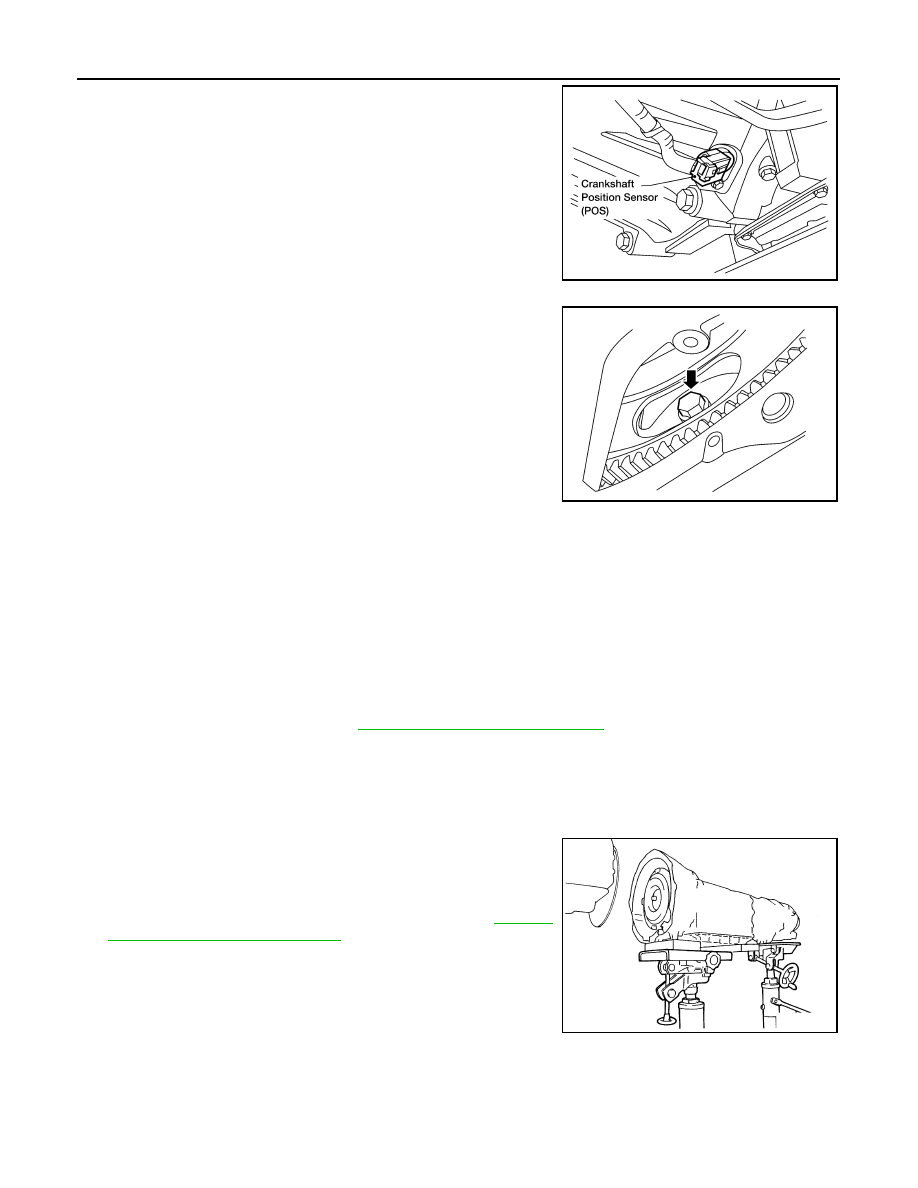
8. Remove crankshaft position sensor (POS) from A/T assembly.

CAUTION:

• Do not subject it to impact by dropping or hitting it.

• Do not disassemble.

• Do not allow metal filings or foreign material to get on the

sensor front edge magnetic area.

• Do not place in an area affected by magnetism.

9. Remove A/T fluid cooler tube from A/T assembly.
10. Remove dust cover from converter housing.

11. Turn crankshaft, and remove the four bolts for drive plate and

torque converter.

CAUTION:

When turning crankshaft, turn it clockwise as viewed from

the front of the engine.

12. Support A/T assembly using transmission jack and Tool.

CAUTION:

When setting the transmission jack, be careful not to allow it to collide against the drain plug.

NOTE:

The actual special service tool may differ from tool shown.

13. Remove cross member using power tool.
14. Tilt the transmission slightly to keep the clearance between body and transmission, then disconnect air

breather hose from A/T fluid charging pipe.

15. Remove air breather hose. Refer to 

TM-166, "Removal and Installation"

.

16. Disconnect A/T assembly connector and transfer unit connector.
17. Remove A/T fluid charging pipe.
18. Plug any openings such as the fluid charging pipe hole.
19. Remove A/T assembly to engine bolts using power tool.

20. Remove A/T assembly with transfer from vehicle.

CAUTION:

• Secure torque converter to prevent it from dropping.

• Secure A/T assembly to transmission jack.

21. Remove transfer from A/T assembly. Refer to 

TM-188,

"Removal and Installation (4WD)"

.

INSPECTION

Installation and Inspection of Torque Converter

LCIA0334E

LCIA0335E

Tool number

:

 (J-47002)

SCIA2203E

TRANSMISSION ASSEMBLY

TM-191

< REMOVAL AND INSTALLATION >

C

E

F

G

H

I

J

K

L

M

A

B

TM

N

O

P

• After inserting a torque converter to a transmission, be sure to

check distance A to ensure it is within specifications.

INSTALLATION

Installation of the remaining components is in the reverse order of removal, while paying attention to the fol-

lowing:

• When installing transmission to the engine, attach the bolts as shown.

CAUTION:

• When replacing an engine or transmission you must make

sure the dowels are installed correctly during re-assembly.

• Improper alignment caused by missing dowels may cause

vibration, oil leaks or breakage of drivetrain components.

NOTE:

*: No.2 bolt also secures air breather vent.

• Align the positions of bolts for drive plate with those of the torque

converter, and temporarily tighten the bolts. Then tighten the bolts

with the specified torque. Refer to 

TM-188, "Removal and Installa-

tion (4WD)"

CAUTION:

• When turning crankshaft, turn it clockwise as viewed from the

front of the engine.

• After converter is installed to drive plate, rotate crankshaft

several turns and check to be sure that transmission rotates

freely without binding.

• Install crankshaft position sensor (POS). 

• After completing installation, check fluid leakage, fluid level, and

the positions of A/T. Refer to 

TM-148, "Checking the A/T Fluid (ATF)"

TM-164, "Checking of A/T Position"

and 

TM-164, "Adjustment of A/T Position"

.

Distance A

: 24.0 mm (0.94 in) or more

SAT017B

Transmission to engine bolts : 113 N·m (12 kg-m, 

83 ft-lb)

LCIA0371E

LCIA0335E

TM-192

< DISASSEMBLY AND ASSEMBLY >

OVERHAUL

DISASSEMBLY AND ASSEMBLY

OVERHAUL

Component

INFOID:0000000005148745

WCIA0661E

OVERHAUL

TM-193

< DISASSEMBLY AND ASSEMBLY >

C

E

F

G

H

I

J

K

L

M

A

B

TM

N

O

P

1.

O-ring

2.

Oil pump cover

3.

O-ring

4.

Oil pump housing

5.

Self-sealing bolts

6.

Torque converter

7.

Converter housing

8.

Oil pump housing oil seal

9.

Bearing race

10. Needle bearing

11. O-ring

12. Front carrier assembly

13. Needle bearing

14. Snap ring

15. Front sun gear

16. 3rd one-way clutch

17. Snap ring

18. Bearing race

19. Needle bearing

20. Seal ring

21. Input clutch assembly

22. Needle bearing

23. Rear internal gear

24. Brake band

25. Mid carrier assembly

26. Needle bearing 

27. Bearing race

28. Rear carrier assembly

29. Needle bearing 

30. Mid sun gear

31. Seal ring

32. Rear sun gear

33. 1st one-way clutch

34. Snap ring

35. Needle bearing

36. High and low reverse clutch hub

37. Snap ring

38. Bearing race

39. Needle bearing


Content   ..  970  971  972  973   ..