Infiniti QX56 (JA60). Manual - part 917


  Index      Infiniti     Infiniti QX56 (JA60) - service repair manual 2010 year


Search            


Content   ..  915  916  917  918   ..


Infiniti QX56 (JA60). Manual - part 917


HYDRAULIC LINE

ST-27

< REMOVAL AND INSTALLATION >

C

D

E

F

H

I

J

K

L

M

A

B

ST

N

O

P

HYDRAULIC LINE

Removal and Installation

INFOID:0000000005147875

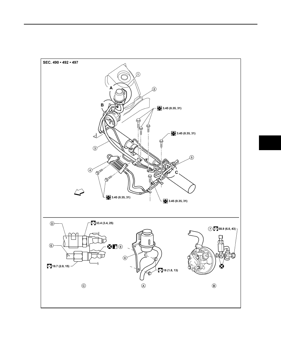
Refer to the following illustration for hydralic line removal.

Installation is in the reverse order of removal.

1.

Reservoir tank

2.

Suction hose

3.

High pressure hose

4.

Oil cooler

5.

Steering gear assembly

6.

Reservoir tank bracket

7.

Eye bolt

8.

O-rings

AWGIA0115GB

ST-28

< REMOVAL AND INSTALLATION >

HYDRAULIC LINE

• Confirm mating marks are aligned with hose and clamp, then cor-

rect if needed.

• To install eye joint, align projection of eye joint with notch of power

steering pump, and attach eye joint to power steering pump prop-

erly. Tighten eye bolt by hand fully, then torque to specification.

SGIA0563E

WGIA0089E

STEERING COLUMN

ST-29

< DISASSEMBLY AND ASSEMBLY >

C

D

E

F

H

I

J

K

L

M

A

B

ST

N

O

P

DISASSEMBLY AND ASSEMBLY

STEERING COLUMN

Disassembly and Assembly

INFOID:0000000005147876

DISASSEMBLY

1. Remove bolt from upper joint, then remove upper joint from steering column assembly.
2. Remove ignition switch tamper resistant self-shear screws with a drill or other suitable tool.

ASSEMBLY

• Assembly is in the reverse order of disassembly.

• Install new tamper resistant self-shear screws.

CAUTION:

Any time the ignition switch has been disconnected, removed

or installed, the keys must be re-registered in the BCM. Refer to

CONSULT-III operation manual IVIS/NVIS.

INSPECTION AFTER ASSEMBLY

When the steering wheel does not turn smoothly, check the steering column as follows:

1.

Steering column assembly

2. Upper joint

3.

Ignition switch

4.

Tamper resistant self-shear screw

WGIA0091E

WGIA0009E

ST-30

< DISASSEMBLY AND ASSEMBLY >

STEERING COLUMN

1. Check the column bearings for damage or unevenness. Lubricate with recommended multi-purpose

grease. Replace the steering column as an assembly, if necessary.

2. Check the column tube for deformation or breakage. Replace the steering column as an assembly, if nec-

essary.

3. If the vehicle has been involved in a collision, or if noise and rat-

tles are heard during a turn, check the length (L) of the column.

If out of specification, replace the steering column as an assem-

bly.

4. Check for proper lubrication, apply grease as necessary.
5. Check for wear around the seal edges, replace the steering col-

umn as an assembly as necessary.

6. Check for corrosion or pitting around the seal sliding area.
7. Replace the seal and shaft in case of seal edge wear or damage.
8. After installing the steering column, check the tilt mechanism for proper operation.

CAUTION:

• Do not exert any load in the axial direction immediately before or after column removal.

• After installation, check smooth steering wheel rotation, without any catches or noise.

WGIA0080E

Steering column length (L)
L

:  Refer  to 

ST-35, "Steering Column"

L

1

: Refer to 

ST-35, "Steering Column"

L

2

: Refer to 

ST-35, "Steering Column"

Range (A)

: Refer to 

ST-35, "Steering Column"

SGIA0475E

WGIA0083E

WGIA0026E


Content   ..  915  916  917  918   ..