Infiniti QX56 (JA60). Manual - part 803


  Index      Infiniti     Infiniti QX56 (JA60) - service repair manual 2010 year


Search            


Content   ..  801  802  803  804   ..


Infiniti QX56 (JA60). Manual - part 803


RSU-22

< REMOVAL AND INSTALLATION >

REAR LOWER LINK & COIL SPRING

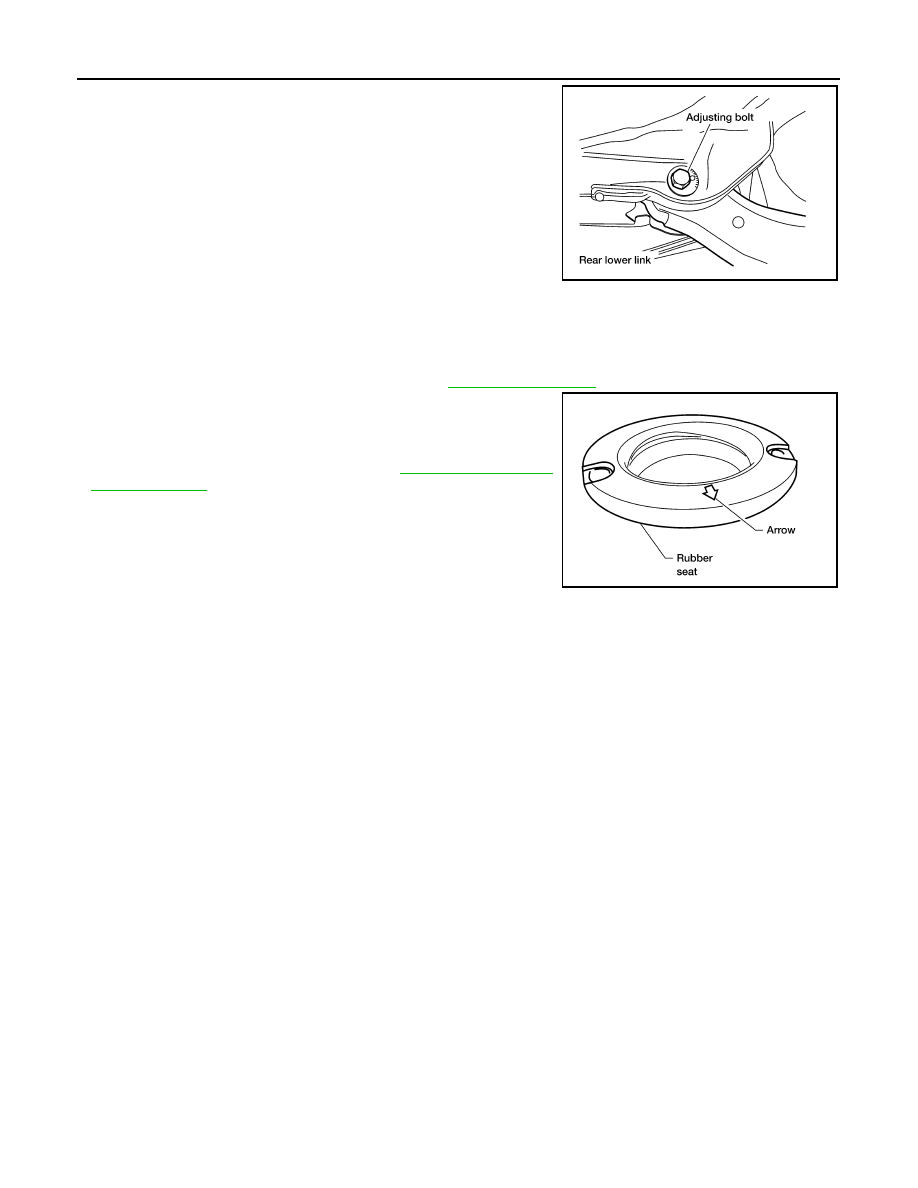
8. Remove the rear lower link adjusting bolt and nut from the rear

suspension member using power tool, then remove the rear

lower link.

INSPECTION AFTER REMOVAL

Check the coil spring and rubber seats for deformation, cracks, or other damage and replace if necessary.

INSTALLATION

Installation is in the reverse order of removal.

• Tighten the nuts and bolts to specification. Refer to 

RSU-9, "Component"

 .

• When installing the upper and lower rubber seats for the rear coil

springs, the arrow embossed on the rubber seats must point out

toward the wheel and tire assembly.

• After installing the rear lower link and coil spring, check the wheel

alignment and adjust if necessary. Refer to 

RSU-6, "Wheel Align-

ment Inspection"

LEIA0009E

LEIA0076E

STABILIZER BAR

RSU-23

< REMOVAL AND INSTALLATION >

C

D

F

G

H

I

J

K

L

M

A

B

RSU

N

O

P

STABILIZER BAR

Removal and Installation

INFOID:0000000005148137

REMOVAL

1. Disconnect the stabilizer bar ends from the connecting rods

using power tool.

2. Remove the stabilizer bar clamps using power tool, and remove

the stabilizer bar bushings.

3. Remove the stabilizer bar.

INSPECTION AFTER REMOVAL

• Check the stabilizer bar for any deformation, cracks, or damage and replace if necessary.

• Check the rubber bushings for deterioration, or cracks and replace if necessary.

INSTALLATION

Installation is in the reverse order of removal.

• Tighten the nuts and bolts to specification. Refer to 

RSU-9, "Component"

 .

• Install the stabilizer bar with the ball joint sockets properly aligned.

• Install the stabilizer bar bushing and clamp so they are positioned

inside of the sideslip prevention clamp on the stabilizer bar.

LEIA0088E

LEIA0089E

SFA449BB

RSU-24

< REMOVAL AND INSTALLATION >

REAR LOAD LEVELING AIR SUSPENSION COMPRESSOR ASSEMBLY

REAR LOAD LEVELING AIR SUSPENSION COMPRESSOR ASSEMBLY

Removal and Installation

INFOID:0000000005148138

Rear Load Leveling Air Suspension System

REMOVAL

1. Use CONSULT-III "EXHAUST SOLENOID" active test to release the air pressure from the rear load level-

ing air suspension system.

2. Disconnect the electrical connectors for the rear load leveling air suspension compressor assembly.
3. Unclip the rubber cover to access the rear load leveling air suspension compressor assembly.
4. Disconnect the rear load leveling air suspension hoses at the

rear load leveling air suspension compressor assembly.

• To disconnect the hoses, push in on the lock ring using a suit-

able tool and pull the hose out.

AWEIA0054GB

1.

Rear load leveling air suspension 
hose, RH

2.

Shock absorber, RH

3.

Height sensor

4.

Rear load leveling air suspension 
hose, LH

5.

Shock absorber, LH

6.

Rear load leveling air suspension 
compressor assembly

Front

LEIA0074E

REAR LOAD LEVELING AIR SUSPENSION COMPRESSOR ASSEMBLY

RSU-25

< REMOVAL AND INSTALLATION >

C

D

F

G

H

I

J

K

L

M

A

B

RSU

N

O

P

5. Remove the four bolts that mount the rear load leveling air sus-

pension compressor assembly to the underbody.

INSTALLATION

Installation is in the reverse order of removal.

• To connect the rear load leveling air suspension hoses, the lock

ring must be fully seated in the fitting. Insert the hose (B) into the

lock ring (A) until the lock ring (A) is touching the hose (B) as

shown. Pull on the hose to check that it is securely inserted.

LEIA0090E

LEIA0078E


Content   ..  801  802  803  804   ..