Infiniti QX56 (JA60). Manual - part 802


  Index      Infiniti     Infiniti QX56 (JA60) - service repair manual 2010 year


Search            


Content   ..  800  801  802  803   ..


Infiniti QX56 (JA60). Manual - part 802


RSU-18

< REMOVAL AND INSTALLATION >

SUSPENSION ARM

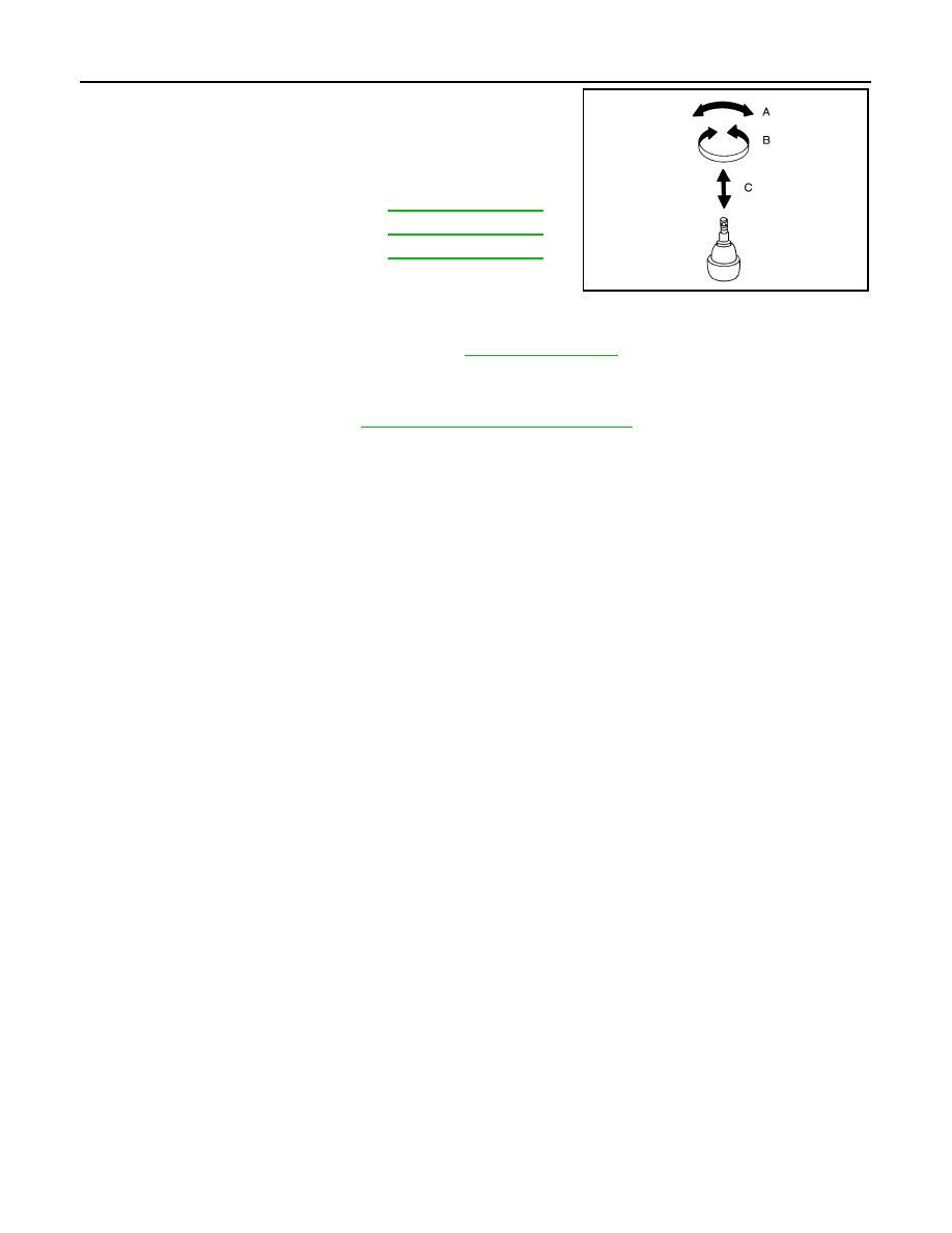
• Check the ball joint. Replace the suspension arm assembly if any

of the following conditions exist:

- Ball stud is worn.

- Joint is hard to swing.

- Play in axial direction is excessive.

INSTALLATION

Installation is in the reverse order of removal.

• Tighten the nuts and bolts to specification. Refer to 

RSU-9, "Component"

 .

• Perform the final tightening of the nuts and bolts for the links (rubber bushing) under unladen condition

(unladen condition means that the fuel tank, engine coolant and lubricants are at the full specification, and

the spare tire, jack, hand tools, and mats are in their designated positions) with the tires on level ground.

• Check the wheel alignment. Refer to 

RSU-6, "Wheel Alignment Inspection"

 .

Swinging force (A)

Refer to 

RSU-29, "Ball Joint"

 .

Turning force (B)

Refer to 

RSU-29, "Ball Joint"

 .

Vertical end play (C)

Refer to 

RSU-29, "Ball Joint"

 .

SFA858A

FRONT LOWER LINK

RSU-19

< REMOVAL AND INSTALLATION >

C

D

F

G

H

I

J

K

L

M

A

B

RSU

N

O

P

FRONT LOWER LINK

Removal and Installation

INFOID:0000000005148135

REMOVAL

1. Remove the wheel and tire assembly using power tool.
2. Use CONSULT-III "EXHAUST SOLENOID" active test to release the air pressure from the rear load level-

ing air suspension system.

3. Remove the shock absorber lower end bolt.
4. Remove the adjusting bolt and nut, and the bolt and nut, from

the front lower link and rear suspension member using power

tool.

5. Remove the front lower link pinch bolt and nut on the knuckle

side using power tool.

6. Disconnect the front lower link from the knuckle using a soft

hammer.

CAUTION:

Do not damage the ball joint with the soft hammer.

7. Remove the front lower link.

INSPECTION AFTER REMOVAL

• Check the front lower link and bushing for any deformation, crack, or damage. Replace if necessary.

• Check the rubber bushing for damage, cracks and deformation. Replace the front lower link and bushing if

necessary.

• Before checking, turn the ball joint at least 10 revolutions so that the ball joint is properly broken in.

LEIA0082E

LEIA0086E

RSU-20

< REMOVAL AND INSTALLATION >

FRONT LOWER LINK

• Check the ball joint. Replace the front lower link if any of the follow-

ing conditions exist:

- Ball stud is worn.

- Joint is hard to swing.

- Play in axial direction is excessive.

INSTALLATION

Installation is in the reverse order of removal.

• Tighten the nuts and bolts to specification. Refer to 

RSU-9, "Component"

 .

• Perform the final tightening of the nuts and bolts for the links (rubber bushing) under unladen condition

(unladen condition means that the fuel tank, engine coolant and lubricants are at the full specification, and

the spare tire, jack, hand tools, and mats are in their designated positions) with the tires on level ground.

• Check the wheel alignment. Refer to 

RSU-6, "Wheel Alignment Inspection"

Swinging force (A)

Refer to 

RSU-29, "Ball Joint"

 .

Turning force (B)

Refer to 

RSU-29, "Ball Joint"

.

Vertical end play (C)

Refer to 

RSU-29, "Ball Joint"

 .

SFA858A

REAR LOWER LINK & COIL SPRING

RSU-21

< REMOVAL AND INSTALLATION >

C

D

F

G

H

I

J

K

L

M

A

B

RSU

N

O

P

REAR LOWER LINK & COIL SPRING

Removal and Installation

INFOID:0000000005148136

REMOVAL

1. Remove the wheel and tire assembly using power tool. Refer to 

WT-49, "Rotation"

 .

2. Use CONSULT-III "EXHAUST SOLENOID" active test to release the air pressure from the rear load level-

ing air suspension system.

3. For removing the LH rear lower link and coil spring, remove the

height sensor arm bracket bolt from the LH rear lower link.

4. Set a suitable jack to relieve the coil spring tension from the rear

lower link.

WARNING:

Do not compress the coil spring when setting the jack.

5. Loosen the rear lower link adjusting bolt and nut connected to

the rear suspension member, using power tool.

6. Remove the rear lower link bolt and nut from the knuckle using

power tool.

7. Slowly lower the suitable jack to release the coil spring tension. Then remove the upper rubber seat, coil

spring, and lower rubber seat from the rear lower link.

LEIA0080E

LEIA0077E

LEIA0009E

LEIA0077E


Content   ..  800  801  802  803   ..