Infiniti QX56 (JA60). Manual - part 696


  Index      Infiniti     Infiniti QX56 (JA60) - service repair manual 2010 year


Search            


Content   ..  694  695  696  697   ..


Infiniti QX56 (JA60). Manual - part 696


MWI

METER SYSTEM

MWI-19

< FUNCTION DIAGNOSIS >

C

D

E

F

G

H

I

J

K

L

M

B

A

O

P

WARNING LAMPS/INDICATOR LAMPS : System Description

INFOID:0000000005146063

OIL PRESSURE WARNING LAMP

• IPDM E/R reads the ON/OFF signals from the oil pressure switch and transmits the oil pressure switch sig-

nal to the combination meter via BCM with the CAN communication line. 

• The combination meter turns the oil pressure warning lamp ON/OFF according to the oil pressure switch sig-

nal received via CAN communication. 

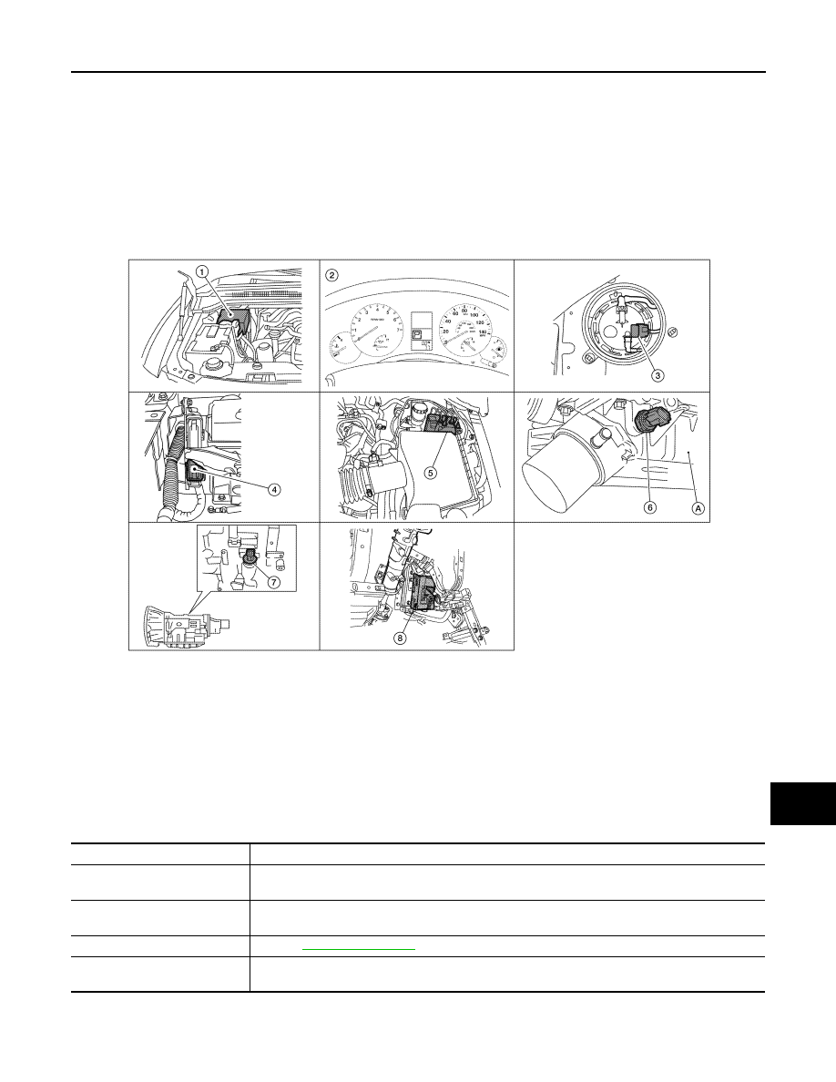
WARNING LAMPS/INDICATOR LAMPS : Component Parts Location

INFOID:0000000005146064

WARNING LAMPS/INDICATOR LAMPS : Component Description

INFOID:0000000005146065

INFORMATION DISPLAY

1.

IPDM E/R E122, E124

2.

Combination meter M23, M24

3.

Fuel level sensor unit and fuel pump 
C5 (view with inspection hole cover re-
moved)

4.

ECM E16 (view with battery removed) 5.

ABS actuator and electric unit (control 
unit) E125

6.

Oil pressure switch F4
A: Oil pan (upper)

7.

A/T assembly F9

8.

BCM M18, M19 (view with instrument 
lower panel LH removed)

AWNIA0201ZZ

Unit

Description

Combination meter

Turns the oil pressure warning lamp ON/OFF according to the oil pressure switch signal received 
from BCM by means of communication. 

IPDM E/R

Reads the ON/OFF signals from the oil pressure switch and transmits the oil pressure switch signal 
to the combination meter via BCM with the CAN communication line. 

Oil pressure switch

Refer to 

MWI-34, "Description"

BCM

Transmits the oil pressure switch signal received from IPDM E/R via CAN communication to the 
combination meter via CAN communication. 

MWI-20

< FUNCTION DIAGNOSIS >

METER SYSTEM

INFORMATION DISPLAY : System Diagram

INFOID:0000000005146066

INFORMATION DISPLAY : System Description

INFOID:0000000005146067

FUNCTION

The information display can indicate the following items.

• Intelligent Key operation information

• Warning/Indication messages (Door/liftgate/liftgate glass open, low fuel, low washer fluid, parking brake, A/T

oil temp) 

DOOR OPEN WARNING

This warning appears when the ignition switch is ON and the front door LH, front door RH, rear door LH, rear

door RH, back door or glass hatch is opened. The BCM receives a door switch signal from the front door

switch LH, front door switch RH, rear door switch LH, rear door switch RH, back door latch and glass hatch

ajar switch. The BCM sends the door switch signal to the combination meter via CAN communication lines.

Then, when the ignition switch is turned ON, the warning message is displayed.

LOW FUEL WARNING

This warning appears when the fuel level in the fuel tank is less than approximately 11.4  (3 US gal, 2.5 Imp

gal). A variable resistor signal is supplied to the combination meter from the fuel level sensor unit to determine

the amount of fuel in the fuel tank.

LOW WINDSHIELD WASHER FLUID WARNING

This warning appears when the windshield washer fluid level is low. When the windshield washer fluid level is

low, the washer level switch provides a ground signal to the combination meter (unified meter control unit).

Once fluid is added, the message will stay on for 30 seconds and then turn off.

PARKING BRAKE INDICATOR

When the parking brake is applied, the parking brake switch provides a ground signal to the combination

meter (unified meter control unit). Then, when the ignition switch is turned ON and vehicle speed is greater

than 7 km/h (4 MPH), the message is displayed.

Refer to Owner’s Manual for additional information display items.

AWNIA0202GB

MWI

METER SYSTEM

MWI-21

< FUNCTION DIAGNOSIS >

C

D

E

F

G

H

I

J

K

L

M

B

A

O

P

INFORMATION DISPLAY : Component Parts Location

INFOID:0000000005146068

INFORMATION DISPLAY : Component Description

INFOID:0000000005146069

1.

IPDM E/R E122, E124

2.

Combination meter M23, M24

3.

Fuel level sensor unit and fuel pump 
C5 (view with inspection hole cover re-
moved)

4.

ECM E16 (view with battery removed) 5.

ABS actuator and electric unit (control 
unit) E125

6.

Oil pressure switch F4
A: Oil pan (upper)

7.

A/T assembly F9

8.

BCM M18, M19 (view with instrument 
lower panel LH removed)

AWNIA0201ZZ

Unit

Description

Combination meter

Controls the information display according to the signal received from each unit. 

Fuel level sensor unit

Refer to 

MWI-32, "Description"

.

BCM

Transmits signals provided by various units to the combination meter via CAN communication line.

Washer level switch

Transmits the washer level signal to the combination meter.

Parking brake switch

Refer to 

MWI-35, "Description"

.

Door switch

Transmits the door switch signals to BCM.

Back door latch (door ajar switch) Transmits the back door switch signal to BCM.

Glass hatch ajar switch

Transmits the glass hatch ajar switch signal to BCM.

TCM

Transmits A/T oil temperature signal to the combination meter with CAN communication line.

MWI-22

< FUNCTION DIAGNOSIS >

DIAGNOSIS SYSTEM (METER)

DIAGNOSIS SYSTEM (METER)

Diagnosis Description

INFOID:0000000005146071

SELF-DIAGNOSIS MODE

The following items can be checked during Combination Meter Self-Diagnosis Mode.

• Gauge sweep and present gauge values.

• Illuminates all odometer/trip meters and A/T indicator segments.

• Illuminates all micro controlled lamps/LEDs regardless of switch position.

• Displays estimated present battery voltage.

• Displays seat belt buckle switch LH status.

OPERATION PROCEDURE

NOTE:

• Once entered, combination meter self-diagnosis mode will function with the ignition switch in ON or START.

Combination meter self-diagnosis mode will exit upon turning the ignition switch to OFF or ACC. 

• If the diagnosis function is activated with trip A displayed, the mileage on trip A is reset to 0000.0. (Trip B

operates the same way.)

To initiate combination meter self-diagnosis mode, refer to the following procedure.

1. Turn the ignition switch ON, while pressing the odometer/trip meter switch for 5 - 8 seconds. When the

diagnosis function is activated, the odometer/trip meter will display tESt.

NOTE:

Check combination meter power supply and ground circuit when self-diagnosis mode of combination meter

does not start. Refer to 

MWI-28, "COMBINATION METER : Diagnosis Procedure"

. Replace combination

meter if normal. Refer to 

MWI-100, "Removal and Installation"

.

COMBINATION METER SELF-DIAGNOSIS MODE FUNCTIONS

To interpret combination meter self-diagnosis mode functions, refer to the following table.

Event

Odometer Display

Description of Test/Data

Notes:

Odometer/trip meter A/B 
switch held from 5 to 8 
seconds (or until re-
leased)

tESt

Initiating self-diagnosis mode

Switch released

GAGE

Performs sweep of all 
gauges, then displays 
present gauge values.

Gauges sweep within 10 seconds

Switch pressed

(All segments illuminated)

Lights all LCD segments. 
Compare with picture.

Switch pressed

bulb

Illuminates all micro-con-
trolled lamps/LEDs.

Part may not be configured for all 
lamps (functions) that turn on dur-
ing test. This is normal.

Switch pressed

r XXXX, FAIL

Return to normal opera-
tion of all lamps/LEDs and 
displays “r XXXX”.

If a malfunction exists, “FAIL” will 
flash.

Switch pressed

nrXXXX

Displays Hex ROM rev as 
stored in NVM.

Switch pressed

EE XX, FAIL

Displays “EE XX”.

If a malfunction exists, “FAIL” will 
flash.

Switch pressed

dtXXXX

Hex coding of final manu-
facturing test date.

AWNIA0203ZZ


Content   ..  694  695  696  697   ..