Infiniti QX56 (JA60). Manual - part 685


  Index      Infiniti     Infiniti QX56 (JA60) - service repair manual 2010 year


Search            


Content   ..  683  684  685  686   ..


Infiniti QX56 (JA60). Manual - part 685


CHASSIS AND BODY MAINTENANCE

MA-33

< ON-VEHICLE MAINTENANCE >

C

D

E

F

G

H

I

J

K

L

M

B

MA

N

O

A

• If a tire balance machine has adhesion balance weight mode settings and drive-in weight mode setting,

select and adjust a drive-in weight mode suitable for wheels.

1. Set wheel on wheel balancer using the center hole as a guide. Start the tire balance machine.
2. When inner and outer imbalance values are shown on the wheel balancer indicator, multiply outer imbal-

ance value by 1.6 to determine balance weight that should be used. Select the outer balance weight with

a value closest to the calculated value and install it to the designated outer position of, or at the desig-

nated angle in relation to the road wheel.

CAUTION:

• Do not install the inner balance weight before installing the outer balance weight.

• Before installing the balance weight, be sure to clean the mating surface of the wheel.

Indicated imbalance value 

× 5/3 = balance weight to be installed

Calculation example:
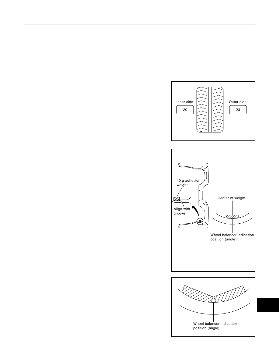
23 g (0.81 oz) 

× 5/3 = 38.33 g (1.35 oz) = 40 g (1.41 oz) balance

weight (closer to calculated balance weight value)

Note that balance weight value must be closer to the calculated

balance weight value.

Example:

37.4 g = 35 g (1.23 oz)

37.5 g = 40 g (1.41 oz)

a. Install balance weight in the position shown.
b. When installing balance weight to wheels, set it into the grooved

area on the inner wall of the wheel as shown so that the balance

weight center is aligned with the wheel balancer indication posi-

tion (angle).

CAUTION:

• Always use Genuine NISSAN adhesion balance weights.

• Balance weights are not reusable; always replace with

new ones.

• Do not install more than three sheets of balance weights.

c. If calculated balance weight value exceeds 50 g (1.76 oz), install

two balance weight sheets in line with each other as shown.

CAUTION:

Do not install one balance weight sheet on top of another.

3. Start wheel balancer again.
4. Install drive-in balance weight on inner side of road wheel in the

wheel balancer indication position (angle).

CAUTION:

Do not install more than two balance weights.

5. Start wheel balancer. Make sure that inner and outer residual

imbalance values are 5 g (0.18 oz) each or below.

• If either residual imbalance value exceeds 5 g (0.18 oz),

repeat installation procedures.

SMA054D

WDIA0060E

SMA056D

MA-34

< ON-VEHICLE MAINTENANCE >

CHASSIS AND BODY MAINTENANCE

Wheel balance (Maximum allowable imbalance):

WHEELS : Rotation

INFOID:0000000005403160

NOTE:

Follow the maintenance schedule for tire rotation service intervals. Refer to 

MA-9, "Schedule 1"

 .

1. Rotate the tires on each side from front to back as shown. Do

not include the spare tire when rotating the tires.

CAUTION:

When installing wheels, tighten them diagonally by dividing

the work two to three times in order to prevent the wheels

from developing any distortion.

2. Adjust the tire pressure to specification. Refer to 

WT-52, "Tire"

 .

3. After the tire rotation, retighten the wheel nuts after the vehicle

has been driven for 1,000 km (600 miles), and also after every

wheel and tire have been installed such as after repairing a flat tire.

BRAKE FLUID LEVEL AND LEAKS
BRAKE FLUID LEVEL AND LEAKS : On Board Inspection

INFOID:0000000005403161

LEVEL CHECK

• Make sure the fluid level in reservoir tank is between MAX and MIN

lines as shown.

• Visually check around reservoir tank for fluid leaks.

• If fluid level is excessively low, check brake system for leaks.

• If brake warning lamp remains illuminated after parking brake

pedal is released, check brake system for fluid leaks.

BRAKE LINES AND CABLES
BRAKE LINES AND CABLES : Checking Brake Line and Cables

INFOID:0000000005259676

1. Check the brake lines and hoses for cracks, deterioration, and

other damage. Replace any damaged parts.

CAUTION:

If brake fluid leaks are visible around the brake line joints,

retighten the joint, or replace damaged parts as necessary.

2. Check for brake fluid leaks by fully depressing brake pedal while

engine is running.

DISC BRAKE

Maximum allowable imbalance

Dynamic (At rim flange)

5 g (0.18 oz) (one side)

Static

10 g (0.35 oz)

 Wheel nut torque

: 133 N·m (14 kg-m, 98 ft-lb)

SMA829C

LFIA0225E

SBR389C

CHASSIS AND BODY MAINTENANCE

MA-35

< ON-VEHICLE MAINTENANCE >

C

D

E

F

G

H

I

J

K

L

M

B

MA

N

O

A

DISC BRAKE : Front Pad Inspection

INFOID:0000000005403162

PAD WEAR

Check pad thickness from the inspection holes on cylinder body.

Check using a scale if necessary.

DISC BRAKE : Front Rotor Inspection

INFOID:0000000005403163

VISUAL

Check surface of disc rotor for uneven wear, cracks, and serious damage. Replace as necessary.

RUNOUT

1. Attach disc rotor to wheel hub using wheel nuts (at two or more

positions). 

2. Inspect runout using a dial gauge placed at 10 mm (0.39 in)

inside the disc edge.

NOTE:

Before measuring, make sure that wheel bearing axial end play

is within the specification. Refer to 

RAX-6, "On-Vehicle Inspec-

tion and Service"

.

3. When runout exceeds limit value, displace mounting positions of disc rotor by one hole. And then find a

position of the minimum value for runout.

4. If runout is outside the specified value after performing the above operation, turn disc rotor using Tool.

THICKNESS

Check thickness of the disc rotor using a micrometer. Replace disc

rotor if thickness is less than the wear limit.

DISC BRAKE : Rear Pad Inspection

INFOID:0000000005403164

PAD WEAR

Standard thickness

: Refer to 

BR-46, "Front Disc 

Brake"

.

Repair limit thickness

: Refer to 

BR-46, "Front Disc 

Brake"

.

WFIA0522E

Runout limit

: Refer to 

BR-46, "Front Disc 

Brake"

.

(with it attached to the vehicle)

Tool number

: 38-PFM90.5 ( — )

BRA0580D

Standard thickness

: Refer to 

BR-46, "Front 

Disc Brake"

.

Repair limit thickness

: Refer to 

BR-46, "Front 

Disc Brake"

.

Thickness variation
(Measured at 8 positions)

: Refer to 

BR-46, "Front 

Disc Brake"

.

SBR020B

MA-36

< ON-VEHICLE MAINTENANCE >

CHASSIS AND BODY MAINTENANCE

Check pad thickness from the inspection holes on cylinder body.

Check using a scale if necessary.

DISC BRAKE : Rear Rotor Inspection

INFOID:0000000005403165

VISUAL

Check surface of disc rotor for uneven wear, cracks, and serious damage. Replace as necessary.

RUNOUT

1. Attach disc rotor to wheel hub using wheel nuts (at two or more

positions). 

2. Inspect runout using dial gauge placed at 10 mm (0.39 in) inside

disc edge.

NOTE:

Before measuring, make sure that wheel bearing axial end play

is within the specification. Refer to 

RAX-6, "On-Vehicle Inspec-

tion and Service"

.

3. When runout exceeds limit value, displace mounting positions of disc rotor by one hole. And then find a

position of the minimum value for runout. 

4. If runout is outside the specified value after performing the above operation, turn disc rotor using Tool.

THICKNESS

Check the thickness of the disc rotor using a micrometer. Replace

disc rotor if the thickness is less than the wear limit.

STEERING GEAR AND LINKAGE
STEERING GEAR AND LINKAGE : Checking Steering Gear and Linkage

INFOID:0000000005403168

STEERING GEAR

Standard thickness

: Refer to 

BR-46, "Rear Disc 

Brake"

.

Repair limit thickness

: Refer to 

BR-46, "Rear Disc 

Brake"

.

BRA0010D

Runout limit 

Refer to 

BR-46, "Rear Disc Brake"

.

(With it attached to the vehicle)

Tool number

: 38-PFM90.5 ( — )

BRA0697D

Standard thickness

: Refer to 

BR-46, "Rear 

Disc Brake"

.

Repair limit thickness

: Refer to 

BR-46, "Rear 

Disc Brake"

.

Thickness variation
(Measured at 8 positions)

: Refer to 

BR-46, "Rear 

Disc Brake"

.

SFIA2284E


Content   ..  683  684  685  686   ..