Infiniti QX56 (JA60). Manual - part 681


  Index      Infiniti     Infiniti QX56 (JA60) - service repair manual 2010 year


Search            


Content   ..  679  680  681  682   ..


Infiniti QX56 (JA60). Manual - part 681


ENGINE MAINTENANCE

MA-17

< ON-VEHICLE MAINTENANCE >

C

D

E

F

G

H

I

J

K

L

M

B

MA

N

O

A

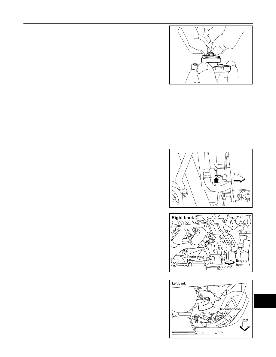
• Pull negative-pressure valve to open it and make sure that it closes

completely when released.

• Make sure that there is no dirt or damage on the valve seat of radi-

ator cap negative-pressure valve.

• Make sure that there are no unusualness in the opening and clos-

ing conditions of negative-pressure valve.

ENGINE COOLANT : Changing Engine Coolant

INFOID:0000000005403134

WARNING:

• To avoid being scalded, never change the coolant when the engine is hot.

• Wrap a thick cloth around the cap to carefully remove the cap. First, turn the cap a quarter of a turn

to release any built-up pressure, then push down and turn the cap all the way to remove it.

DRAINING ENGINE COOLANT

1. Turn ignition switch ON and set temperature control lever all the way to HOT position or the highest tem-

perature position. Wait 10 seconds and turn ignition switch OFF.

2. Remove the engine front undercover using power tool.
3. Open the radiator drain plug at the bottom of the radiator, and

remove the radiator filler cap. This is the only step required

when partially draining the cooling system (radiator only). 

CAUTION:

Do not to allow the coolant to contact the drive belts. 

4. When draining all of the coolant in the system for engine

removal or repair, it is necessary to drain the cylinder block.

Remove the RH cylinder block drain plug to drain the right bank

and the oil cooler hose to drain the left bank as shown.

SMA967B

WBIA0391E

PBIC0146E

WBIA0392E

MA-18

< ON-VEHICLE MAINTENANCE >

ENGINE MAINTENANCE

5. Remove the reservoir tank to drain the engine coolant, then clean the reservoir tank before installing it.
6. Check the drained coolant for contaminants such as rust, corrosion or discoloration.

If the coolant is contaminated, flush the engine cooling system. Refer to 

MA-17, "ENGINE COOLANT :

Changing Engine Coolant"

.

REFILLING ENGINE COOLANT

1. Close the radiator drain plug. Install the reservoir tank, cylinder block drain plug, and the oil cooler hose, if

removed for a total system drain or for engine removal or repair.

• The radiator must be completely empty of coolant and water.

• Apply sealant to the threads of the cylinder block drain plug. Use Genuine High Performance Thread

Sealant or equivalent. Refer to 

GI-15, "Recommended Chemical Products and Sealants"

.

2. Set the vehicle heater controls to the full HOT and heater ON position. Turn the vehicle ignition ON with

the engine OFF as necessary to activate the heater mode.

3. Remove the vented reservoir cap and replace it with a non-vented reservoir cap before filling the cooling

system.

4. Install the Tool by installing the radiator cap adapter onto the

radiator neck opening. Then attach the gauge body assembly

with the refill tube and the venturi assembly to the radiator cap

adapter.

5. Insert the refill hose into the coolant mixture container that is

placed at floor level. Make sure the ball valve is in the closed

position. 

• Use Genuine NISSAN Long Life Anti-freeze coolant or equiva-

lent, mixed 50/50 with distilled water or demineralized water.

Refer to 

MA-13, "Fluids and Lubricants"

6. Install an air hose to the venturi assembly, the air pressure must

be within specification. 

CAUTION:

The compressed air supply must be equipped with an air

dryer.

7. The vacuum gauge will begin to rise and there will be an audible hissing noise. During this process open

the ball valve on the refill hose slightly. Coolant will be visible rising in the refill hose. Once the refill hose is

full of coolant, close the ball valve. This will purge any air trapped in the refill hose.

8. Continue to draw the vacuum until the gauge reaches 28 inches

of vacuum. The gauge may not reach 28 inches in high altitude

locations, use the vacuum specifications based on the altitude

above sea level.

Radiator drain plug

: Refer to 

MA-17

.

RH cylinder block drain plug

: Refer to 

EM-83

.

Tool number

: KV991J0070 (J-45695)

Cooling system capacity 
(with reservoir)

: Refer to 

MA-13, "Fluids 

and Lubricants"

.

Compressed air 
supply pressure

: 5.7 - 8.5 kPa (5.6 - 8.4 kg/cm

2

, 80 

- 120 psi)

LLIA0058E

Altitude above sea level

Vacuum gauge reading

0 - 100 m (328 ft)

: 28 inches of vacuum

300 m (984 ft)

: 27 inches of vacuum

LLIA0057E

ENGINE MAINTENANCE

MA-19

< ON-VEHICLE MAINTENANCE >

C

D

E

F

G

H

I

J

K

L

M

B

MA

N

O

A

9. When the vacuum gauge has reached the specified amount, disconnect the air hose and wait 20 seconds

to see if the system loses any vacuum. If the vacuum level drops, perform any necessary repairs to the

system and repeat steps 6 - 8 to bring the vacuum to the specified amount. Recheck for any leaks. 

10. Place the coolant container (with the refill hose inserted) at the same level as the top of the radiator. Then

open the ball valve on the refill hose so the coolant will be drawn up to fill the cooling system. The cooling

system is full when the vacuum gauge reads zero.

CAUTION:

Do not allow the coolant container to get too low when filling, to avoid air from being drawn into

the cooling system. 

11. Remove the Tool from the radiator neck opening and install the radiator cap.
12. Remove the non-vented reservoir cap.
13. Fill the cooling system reservoir tank to the specified level. Run the engine to warm up the cooling system

and top up the system as necessary before installing the vented reservoir cap.

FLUSHING COOLING SYSTEM

1. Drain the water from the engine cooling system. Refer to 

MA-17, "ENGINE COOLANT : Changing Engine

Coolant"

.

2. Fill the radiator and the reservoir tank (to the “MAX” line), with water. Reinstall the radiator cap and leave

the vented reservoir cap off.

3. Run the engine until it reaches normal operating temperature.
4. Press the engine accelerator two or three times under no-load.
5. Stop the engine and wait until it cools down.
6. Drain the water from the engine cooling system. Refer to 

MA-17, "ENGINE COOLANT : Changing Engine

Coolant"

.

7. Repeat steps 2 through 6 until clear water begins to drain from the radiator.

FUEL LINES
FUEL LINES : Checking Fuel Line

INFOID:0000000005403135

Inspect fuel lines, fuel filler cap and fuel tank for improper attach-

ment, leaks, cracks, damage, loose connections, chafing or deterio-

ration.

If necessary, repair or replace damaged parts.

FUEL FILTER
FUEL FILTER : Changing Fuel Filter

INFOID:0000000005259654

The fuel filter is part of the fuel level sensor unit, fuel filter and fuel pump assembly and cannot be replaced

separately. Refer to 

FL-7, "Removal and Installation"

.

WARNING:

Before replacing the fuel filter, release the fuel pressure from the fuel system. Refer to 

EC-489, "Fuel

Pressure Check"

.

AIR CLEANER FILTER

500 m (1,641 ft)

: 26 inches of vacuum

1,000 m (3,281 ft)

: 24 - 25 inches of vacuum

SMA803A

MA-20

< ON-VEHICLE MAINTENANCE >

ENGINE MAINTENANCE

AIR CLEANER FILTER : Exploded View

INFOID:0000000005403138

AIR CLEANER FILTER : Removal and Installation (Viscous paper type)

INFOID:0000000005403139

REMOVAL

NOTE:

• The viscous paper type filter does not need cleaning between replacement intervals.

• Replace the air filter as necessary for periodic maintenance. Refer to 

MA-9, "Introduction of Periodic Mainte-

nance"

.

1. Remove the air cleaner case (upper).
2. Remove the air cleaner filter from the air cleaner case (lower).

INSTALLATION

1. Install the new air cleaner filter in the air cleaner case (lower).
2. Install the air cleaner case (upper).

ENGINE OIL
ENGINE OIL : Inspection

INFOID:0000000005403140

OIL LEVEL

• Before starting the engine make sure the vehicle is parked on a flat

and level surface, then check the oil level. If the engine is already

running, turn it off and allow 10 minutes before checking.

• Check that the oil level is within the low (L) to high (H) range as

indicated on the dipstick.

• If the engine oil level is out of range, add oil as necessary. Refer to

MA-13, "Fluids and Lubricants"

.

OIL APPEARANCE

• Check the engine oil for a white milky appearance or excessive contamination.

1.

Air cleaner case (lower)

2.

Air cleaner filter

3.

Air cleaner case (upper)

4.

Air duct and resonator assembly

Front

ALBIA0413GB

SMA954C


Content   ..  679  680  681  682   ..