Infiniti QX56 (JA60). Manual - part 647
IP-12
< ON-VEHICLE REPAIR >
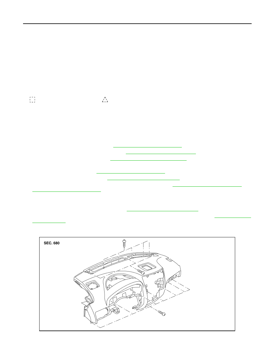
INSTRUMENT PANEL ASSEMBLY
Removal and Installation
INFOID:0000000005147362
REMOVAL
CAUTION:
Disconnect both the negative and positive battery terminals in advance.
1. Disconnect both negative and positive terminals, then wait at least 3 minutes.
2. Remove front center console. Refer to
IP-20, "Removal and Installation"
3. Remove steering column assembly. Refer to
ST-20, "Removal and Installation"
4. Remove combination meter. Refer to
MWI-100, "Removal and Installation"
.
5. Remove instrument panel upper cover and disconnect rear sonar speaker.
6. Remove cluster lid C. Refer to
IP-15, "Removal and Installation"
7. Remove display assembly. Refer to
AV-169, "Removal and Installation"
.
8. Remove instrument lower/upper panel RH and glove box. Refer to
IP-17, "Removal and Installation"
IP-18, "Removal and Installation"
.
9. Release the clips, disconnect the optical sensor harness and remove defroster grille.
10. Release the clips, disconnect the connectors and remove RH, LH, and center speakers.
11. Remove RH/LH front pillar finishers. Refer to
INT-14, "Removal and Installation"
12. Remove the passenger air bag module nuts and disconnect the connectors. Refer to
13. Disconnect remaining optional equipment connectors (if equipped).
14. Remove instrument panel and pad assembly screws.
15. Release instrument panel and pad assembly lifting rearward away from steering member, then carefully
remove through front door opening.
1.
Defroster grille
2.
Center speaker grille
3.
Speaker center
4.
Speaker grille outer
5.
Speaker outer
6.
Instrument panel upper cover
7.
Instrument panel and pad assembly 8.
Side ventilator assembly LH
9.
Combination meter
10. Instrument upper panel LH
11.
Cluster lid A
12. Key cylinder escutcheon
13. Lower knee protector
14.
Instrument lower panel LH
15. Steering column cover upper
16. Steering column cover lower
17.
Cluster lid C lower
18. 4WD switch (if equipped)
19. Hazard switch
20.
Cluster lid C
21. Instrument lower cover RH
22. Fuse access cover
23.
Glove box
24. Instrument lower panel RH
25. Audio switch RH
26.
A/C and AV switch assembly
27. Audio unit
28. Audio switch LH
29.
Center ventilator assembly LH
30. Display assembly
31. Center ventilator assembly RH
32.
Side ventilator assembly RH
33. Instrument upper panel RH
Metal clip
Clip
ALJIA0083ZZ