Infiniti QX56 (JA60). Manual - part 589
AUTOMATIC AIR CONDITIONER SYSTEM
HAC-13
< FUNCTION DIAGNOSIS >
[AUTOMATIC AIR CONDITIONER]
C
D
E
F
G
H
J
K
L
M
A
B
HAC
N
O
P
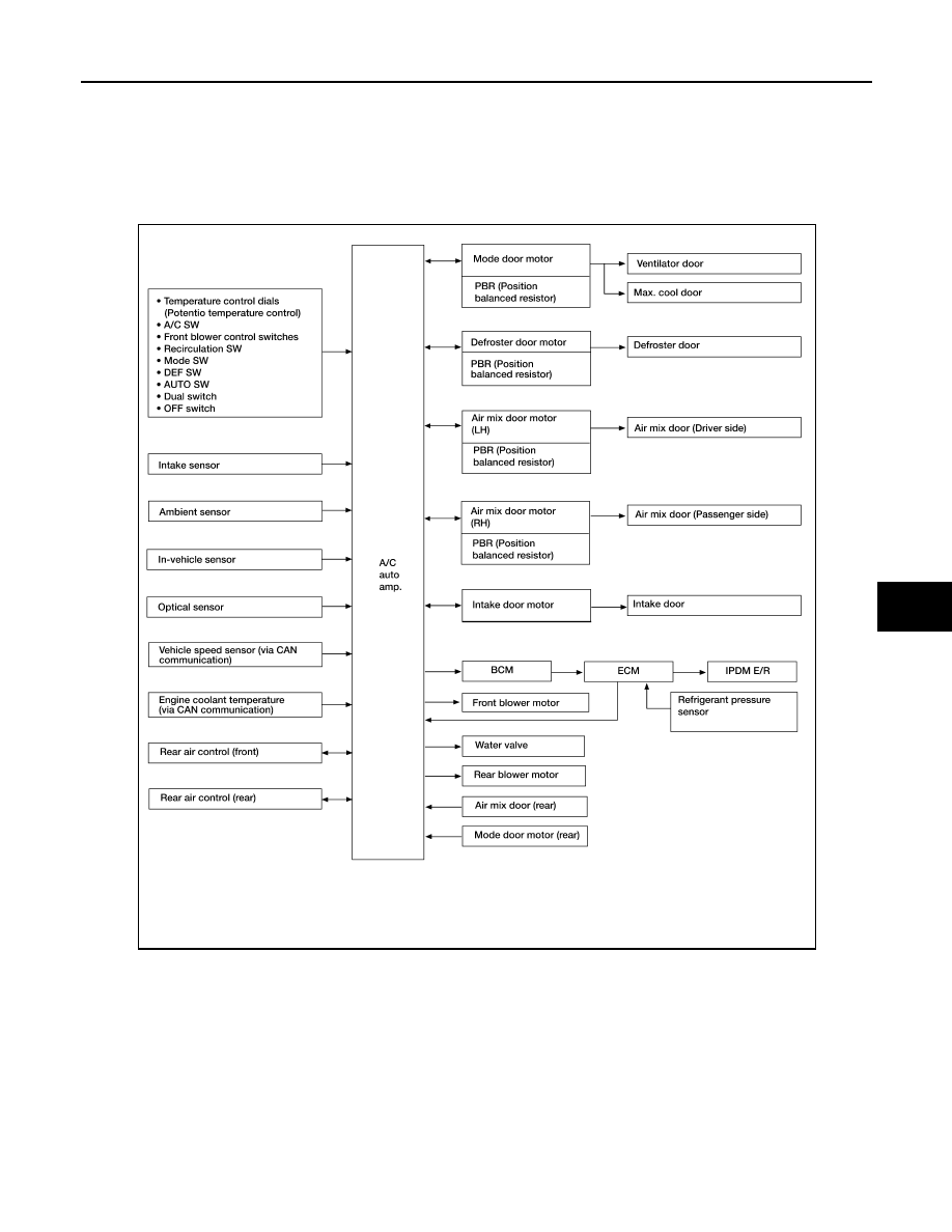
AUTOMATIC AIR CONDITIONER SYSTEM
Control System Diagram
INFOID:0000000005147675
CONTROL SYSTEM
The control system consists of input sensors, switches, the A/C auto amp.(microcomputer) and outputs.
The relationship of these components is shown in the figure below:
Control System Description
INFOID:0000000005147676
CONTROL OPERATION
AWIIA0088GB