Infiniti QX56 (JA60). Manual - part 581
REFRIGERATION SYSTEM
HA-29
< ON-VEHICLE REPAIR >
C
D
E
F
G
H
J
K
L
M
A
B
HA
N
O
P
ON-VEHICLE REPAIR
REFRIGERATION SYSTEM
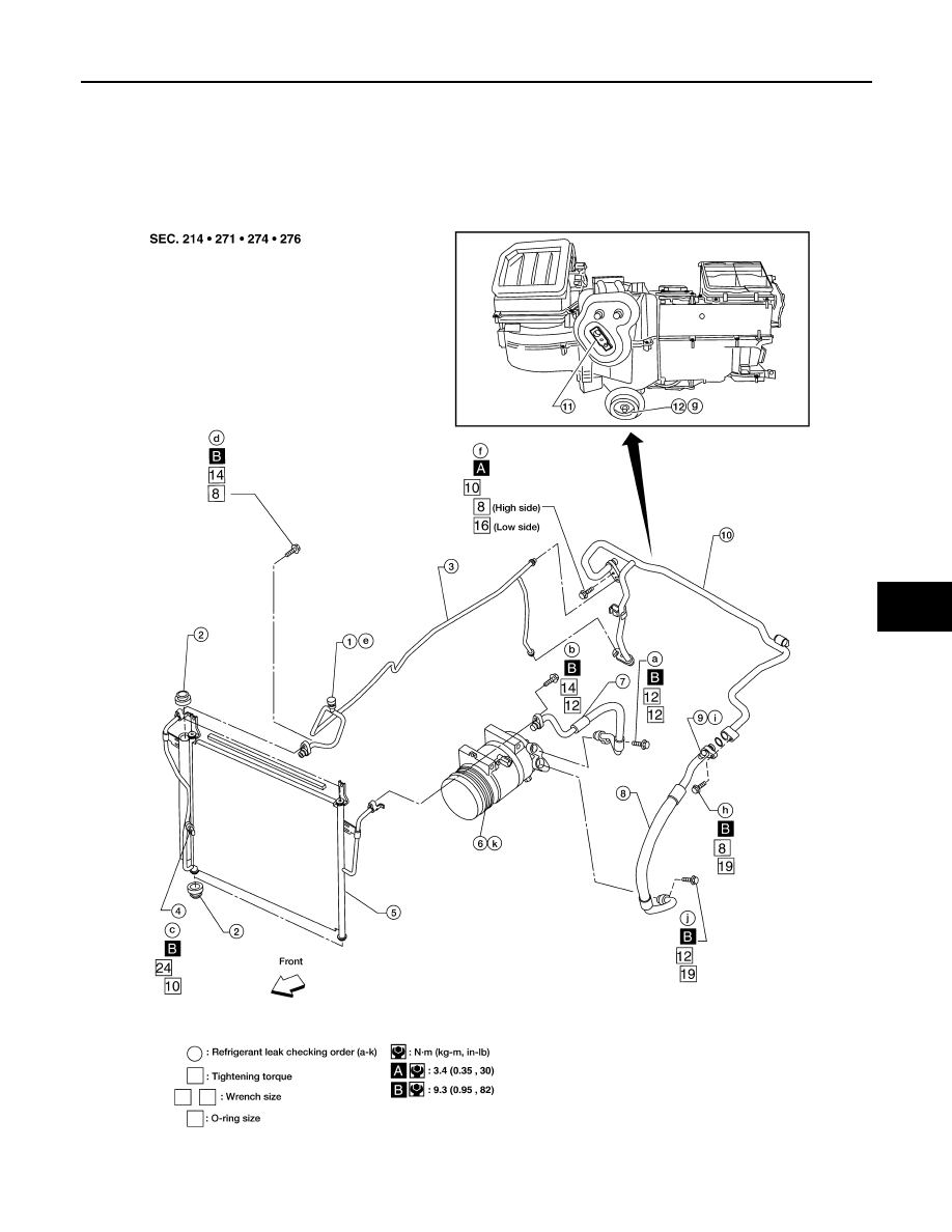
Component
INFOID:0000000005147652
Front A/C System
WJIA1578E
|
|
|
REFRIGERATION SYSTEM HA-29 < ON-VEHICLE REPAIR > C D E F G H J K L M A B HA N O P ON-VEHICLE REPAIR REFRIGERATION SYSTEM Component INFOID:0000000005147652 Front A/C System WJIA1578E |