Infiniti QX56 (JA60). Manual - part 503
PARKING LAMP CIRCUIT
EXL-41
< COMPONENT DIAGNOSIS >
C
D
E
F
G
H
I
J
K
M
A
B
EXL
N
O
P
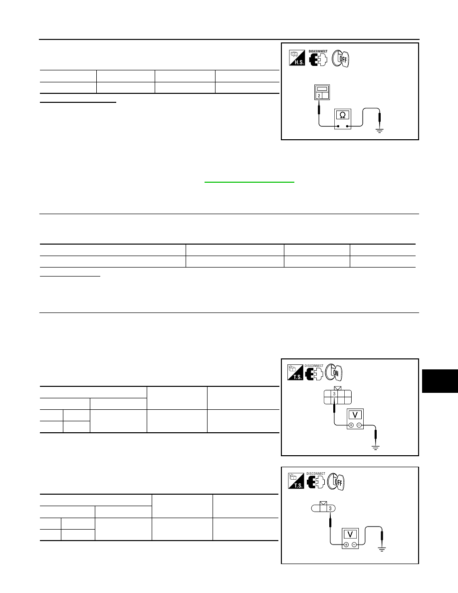
3. Check continuity between the license plate lamp harness con-
nectors and ground.
Does continuity exist?
YES
>> Inspect the parking lamp bulb.
NO
>> Repair the harness.
Diagnosis Procedure - With Daytime Light System
INFOID:0000000005146653
Regarding Wiring Diagram information, refer to
.
1.
CHECK PARKING LAMP FUSES
1. Turn the ignition switch OFF.
2. Check that the following fuses are not open.
Is the fuse open?
YES
>> Repair the harness and replace the fuse.
NO
>> GO TO 2.
2.
CHECK TAIL LAMP RELAY OUTPUT (VOLTAGE)
1. Turn the ignition switch OFF.
2. Disconnect the front combination lamp connector, rear combination lamp connector and license plate
lamp connector.
3. Turn the ignition switch ON.
4. Turn the parking lamps ON.
5. With the parking lamps ON, check voltage between the front
combination lamp connectors and ground.
6. With the parking lamps ON, check voltage between the rear
combination lamp connectors and ground.
Connector
Terminal
—
Continuity
D703
2
Ground
Yes
WKIA4615E
Unit
Location
Fuse No.
Capacity
Parking lamps
IPDM E/R
37
10A
(+)
(
−)
Voltage
Connector
Terminal
LH
E6
3
Ground
Battery voltage
RH
E108
ALLIA0857ZZ
(+)
(
−)
Voltage
Connector
Terminal
LH
B70
3
Ground
Battery voltage
RH
B130
AWLIA1622ZZ