Infiniti QX56 (JA60). Manual - part 388


  Index      Infiniti     Infiniti QX56 (JA60) - service repair manual 2010 year


Search            


Content   ..  386  387  388  389   ..


Infiniti QX56 (JA60). Manual - part 388


EC-204

< COMPONENT DIAGNOSIS >

[VK56DE]

P0335 CKP SENSOR (POS)

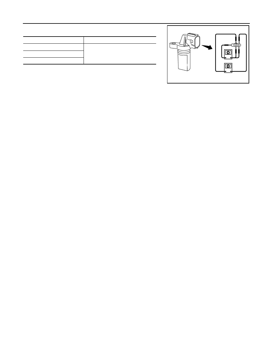
5. Check resistance as shown in the figure.

Terminal No. (Polarity)

Resistance 

Ω [at 25°C (77°F)]

1 (+) - 2 (-)

Except 0 or 

1 (+) - 3 (-)

2 (+) - 3 (-)

PBIB0564E

P0340 CMP SENSOR (PHASE)

EC-205

< COMPONENT DIAGNOSIS >

[VK56DE]

C

D

E

F

G

H

I

J

K

L

M

A

EC

N

P

O

P0340 CMP SENSOR (PHASE)

Component Description

INFOID:0000000005149224

The camshaft position sensor (PHASE) senses the protrusion of

exhaust valve cam sprocket to identify a particular cylinder. The

camshaft position sensor (PHASE) senses the piston position.

When the crankshaft position sensor (POS) system becomes inoper-

ative, the camshaft position sensor (PHASE) provides various con-

trols of engine parts instead, utilizing timing of cylinder identification

signals.

The sensor consists of a permanent magnet and Hall IC.

When engine is running, the high and low parts of the teeth cause

the gap with the sensor to change.

The changing gap causes the magnetic field near the sensor to

change.

Due to the changing magnetic field, the voltage from the sensor changes.

ECM receives the signals as shown in the figure.

On Board Diagnosis Logic

INFOID:0000000005149225

DTC Confirmation Procedure

INFOID:0000000005149226

NOTE:

If DTC Confirmation Procedure has been previously conducted, always perform the following procedure

before conducting the next step.
1. Turn ignition switch OFF and wait at least 10 seconds.
2. Turn ignition switch ON.
3. Turn ignition switch OFF and wait at least 10 seconds.
TESTING CONDITION:

Before performing the following procedure, confirm that battery voltage is more than 10.5V with igni-

tion switch ON.

1. Turn ignition switch ON.

2. Crank engine for at least 2 seconds and run it for at least 5 seconds at idle speed.

3. Check 1st trip DTC.

4. If 1st trip DTC is detected, go to 

EC-206, "Diagnosis Procedure"

.

If 1st trip DTC is not detected, go to next step.

5. Maintaining engine speed at more than 800 rpm for at least 5 seconds.

6. Check 1st trip DTC.

7. If 1st trip DTC is detected, go to 

EC-206, "Diagnosis Procedure"

.

PBIB0562E

PBIB3459E

DTC No.

Trouble diagnosis name

DTC detecting condition

Possible cause

P0340
0340

Camshaft position sen-
sor (PHASE) circuit

• The cylinder No. signal is not sent to ECM for 

the first few seconds during engine cranking.

• The cylinder No. signal is not sent to ECM 

during engine running.

• The cylinder No. signal is not in the normal 

pattern during engine running.

• Harness or connectors

(The sensor circuit is open or shorted)

• Camshaft position sensor (PHASE)
• Camshaft (Exhaust)
• Starter motor (Refer to 

STR-19

.)

• Starting system circuit (Refer to 

STR-19

.)

• Dead (Weak) battery

EC-206

< COMPONENT DIAGNOSIS >

[VK56DE]

P0340 CMP SENSOR (PHASE)

Diagnosis Procedure

INFOID:0000000005149227

1.

CHECK STARTING SYSTEM

Turn ignition switch to START position.

Yes or No

Yes

>> GO TO 2.

No

>> Check starting system. (Refer to 

STR-19

.)

2.

CHECK GROUND CONNECTIONS

1. Turn ignition switch OFF.

2. Loosen and retighten three ground screws on the body.

Refer to 

EC-85, "Ground Inspection"

.

OK or NG

OK

>> GO TO 3.

NG

>> Repair or replace ground connections.

3.

CHECK CAMSHAFT POSITION (CMP) SENSOR (PHASE) POWER SUPPLY CIRCUIT

1. Disconnect camshaft position (CMP) sensor (PHASE) (2) har-

ness connector.

-

Radiator hose (1)

2. Turn ignition switch ON.

3. Check voltage between CMP sensor (PHASE) terminal 3 and

ground with CONSULT-III or tester.

OK or NG

OK

>> GO TO 5.

NG

>> GO TO 4.

4.

DETECT MALFUNCTIONING PART

Check the following.

• Harness connectors F32, E2

Does the engine turn over?
Does the starter motor operate?

BBIA0354E

BBIA0740E

Voltage: Battery voltage

SEF481Y

P0340 CMP SENSOR (PHASE)

EC-207

< COMPONENT DIAGNOSIS >

[VK56DE]

C

D

E

F

G

H

I

J

K

L

M

A

EC

N

P

O

• Harness for open or short between camshaft position sensor (PHASE) and ECM

• Harness for open or short between camshaft position sensor (PHASE) and IPDM E/R

>> Repair open circuit or short to ground or short to power in harness or connectors.

5.

CHECK CMP SENSOR (PHASE) GROUND CIRCUIT FOR OPEN AND SHORT

1. Turn ignition switch OFF.

2. Check harness continuity between CMP sensor (PHASE) terminal 1 and ground.

Refer to wiring Diagram.

3. Also check harness for short to power.
OK or NG

OK

>> GO TO 7.

NG

>> GO TO 6.

6.

DETECT MALFUNCTIONING PART

Check the following.

• Harness connectors F32, E2

• Harness for open or short between CMP sensor (PHASE) and ground

>> Repair open circuit or short to power in harness or connectors.

7.

CHECK CMP SENSOR (PHASE) INPUT SIGNAL CIRCUIT FOR OPEN AND SHORT

1. Disconnect ECM harness connector.

2. Check harness continuity between ECM terminal 14 and CMP sensor (PHASE) terminal 2. 

Refer to Wiring Diagram.

3. Also check harness for short to ground and short to power.
OK or NG

OK

>> GO TO 8.

NG

>> Repair open circuit or short to ground or short to power in harness or connectors.

8.

CHECK CAMSHAFT POSITION SENSOR (PHASE)

Refer to 

EC-207, "Component Inspection"

.

OK or NG

OK

>> GO TO 9.

NG

>> Replace camshaft position sensor (PHASE).

9.

CHECK INTERMITTENT INCIDENT

Refer to 

GI-35, "How to Check Terminal"

 and 

GI-38, "Intermittent Incident"

.

>> INSPECTION END

Component Inspection

INFOID:0000000005149228

CAMSHAFT POSITION SENSOR (PHASE)

1. Loosen the fixing bolt of the sensor.
2. Disconnect camshaft position sensor (PHASE) harness connector.
3. Remove the sensor.

Continuity should exist.

Continuity should exist.


Content   ..  386  387  388  389   ..