Infiniti QX56 (JA60). Manual - part 345


  Index      Infiniti     Infiniti QX56 (JA60) - service repair manual 2010 year


Search            


Content   ..  343  344  345  346   ..


Infiniti QX56 (JA60). Manual - part 345


EC-32

< FUNCTION DIAGNOSIS >

[VK56DE]

AIR CONDITIONING CUT CONTROL

AIR CONDITIONING CUT CONTROL

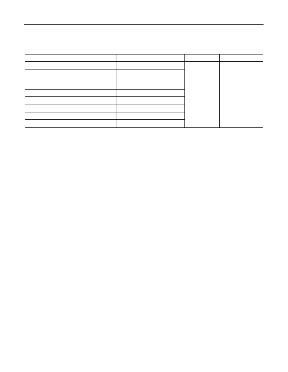
Input/Output Signal Chart

INFOID:0000000005149066

*1: This signal is sent to the ECM through CAN communication line.
*2: ECM determines the start signal status by the signals of engine speed and battery voltage.

System Description

INFOID:0000000005149067

This system improves engine operation when the air conditioner is used.

Under the following conditions, the air conditioner is turned OFF.

• When the accelerator pedal is fully depressed.

• When cranking the engine.

• At high engine speeds.

• When the engine coolant temperature becomes excessively high.

• When operating power steering during low engine speed or low vehicle speed.

• When engine speed is excessively low.

• When refrigerant pressure is excessively low or high.

Sensor

Input Signal to ECM

ECM function

Actuator

Air conditioner switch

Air conditioner ON signal*

1

Air conditioner 
cut control

Air conditioner relay

Accelerator pedal position sensor

Accelerator pedal position

Crankshaft position sensor (POS)
Camshaft position sensor (PHASE)

Engine speed*

2

Engine coolant temperature sensor

Engine coolant temperature

Battery

Battery voltage*

2

Refrigerant pressure sensor

Refrigerant pressure

Power steering pressure sensor

Power steering operation

Wheel sensor

Vehicle speed*

1

AUTOMATIC SPEED CONTROL DEVICE (ASCD)

EC-33

< FUNCTION DIAGNOSIS >

[VK56DE]

C

D

E

F

G

H

I

J

K

L

M

A

EC

N

P

O

AUTOMATIC SPEED CONTROL DEVICE (ASCD)

System Description

INFOID:0000000005149068

INPUT/OUTPUT SIGNAL CHART

*: This signal is sent to the ECM through CAN communication line

BASIC ASCD SYSTEM

Refer to Owner's Manual for ASCD operating instructions.

Automatic Speed Control Device (ASCD) allows a driver to keep vehicle at predetermined constant speed

without depressing accelerator pedal. Driver can set vehicle speed in advance between approximately 40 km/

h (25 MPH) and 144 km/h (89 MPH).

ECM controls throttle angle of electric throttle control actuator to regulate engine speed.

Operation status of ASCD is indicated by CRUISE indicator and SET indicator in combination meter. If any

malfunction occurs in ASCD system, it automatically deactivates control.

NOTE:

Always drive vehicle in safe manner according to traffic conditions and obey all traffic laws.

SET OPERATION

Press MAIN switch. (The CRUISE indicator in combination meter illuminates.)

When vehicle speed reaches a desired speed between approximately 40 km/h (25 MPH) and 144 km/h (89

MPH), press SET/COAST switch. (Then SET indicator in combination meter illuminates.)

ACCELERATE OPERATION

If the RESUME/ACCELERATE switch is pressed during cruise control driving, increase the vehicle speed until

the switch is released or vehicle speed reaches maximum speed controlled by the system.

And then ASCD will keep the new set speed.

CANCEL OPERATION

When any of following conditions exist, cruise operation will be canceled.

• CANCEL switch is pressed

• More than 2 switches at ASCD steering switch are pressed at the same time (Set speed will be cleared)

• Brake pedal is depressed

• Selector lever is changed to N, P, R position

• Vehicle speed decreased to 13 km/h (8 MPH) lower than the set speed

• VDC system is operated

When the ECM detects any of the following conditions, the ECM will cancel the cruise operation and inform

the driver by blinking indicator lamp.

• Engine coolant temperature is slightly higher than the normal operating temperature, CRUISE indicator may

blink slowly.

When the engine coolant temperature decreases to the normal operating temperature, CRUISE indicator will

stop blinking and the cruise operation will be able to work by pressing SET/COAST switch or RESUME/

ACCELERATE switch.

• Malfunction for some self-diagnoses regarding ASCD control: SET indicator will blink quickly.

If MAIN switch is turned to OFF during ASCD is activated, all of ASCD operations will be canceled and vehicle

speed memory will be erased.

COAST OPERATION

When the SET/COAST switch is pressed during cruise control driving, decrease vehicle set speed until the

switch is released. And then ASCD will keep the new set speed.

RESUME OPERATION

Sensor

Input signal to ECM

ECM function

Actuator

ASCD brake switch

Brake pedal operation

ASCD vehicle speed control

Electric throttle control 
actuator

Stop lamp switch

Brake pedal operation

ASCD steering switch

ASCD steering switch operation

Wheel sensor

Vehicle speed*

TCM

Gear position

Powertrain revolution*

EC-34

< FUNCTION DIAGNOSIS >

[VK56DE]

AUTOMATIC SPEED CONTROL DEVICE (ASCD)

When the RESUME/ACCELERATE switch is pressed after cancel operation other than pressing MAIN switch

is performed, vehicle speed will return to last set speed. To resume vehicle set speed, vehicle condition must

meet following conditions.

• Brake pedal is released

• A/T selector lever is in other than P and N positions

• Vehicle speed is greater than 40 km/h (25 MPH) and less than 144 km/h (89 MPH)

Component Description

INFOID:0000000005149069

ASCD STEERING SWITCH

Refer to 

EC-332

.

ASCD BRAKE SWITCH

Refer to 

EC-344

, and 

EC-388

.

STOP LAMP SWITCH

Refer to 

EC-344

EC-353

 and 

EC-388

.

ELECTRIC THROTTLE CONTROL ACTUATOR 

Refer to 

EC-356

EC-359

EC-363

 and 

EC-365

.

ASCD INDICATOR

Refer to 

EC-391

.

CAN COMMUNICATION

EC-35

< FUNCTION DIAGNOSIS >

[VK56DE]

C

D

E

F

G

H

I

J

K

L

M

A

EC

N

P

O

CAN COMMUNICATION

System Description

INFOID:0000000005149070

CAN (Controller Area Network) is a serial communication line for real time application. It is an on-vehicle mul-

tiplex communication line with high data communication speed and excellent error detection ability. Many elec-

tronic control units are equipped onto a vehicle, and each control unit shares information and links with other

control units during operation (not independent). In CAN communication, control units are connected with 2

communication lines (CAN H line, CAN L line) allowing a high rate of information transmission with less wiring.

Each control unit transmits/receives data but selectively reads required data only.

Refer to 

LAN-44, "CAN System Specification Chart"

, about CAN communication for detail.


Content   ..  343  344  345  346   ..