Infiniti QX56 (JA60). Manual - part 333


  Index      Infiniti     Infiniti QX56 (JA60) - service repair manual 2010 year


Search            


Content   ..  331  332  333  334   ..


Infiniti QX56 (JA60). Manual - part 333


REAR FINAL DRIVE

DLN-255

< DISASSEMBLY AND ASSEMBLY >

[REAR FINAL DRIVE: R230]

C

E

F

G

H

I

J

K

L

M

A

B

DLN

N

O

P

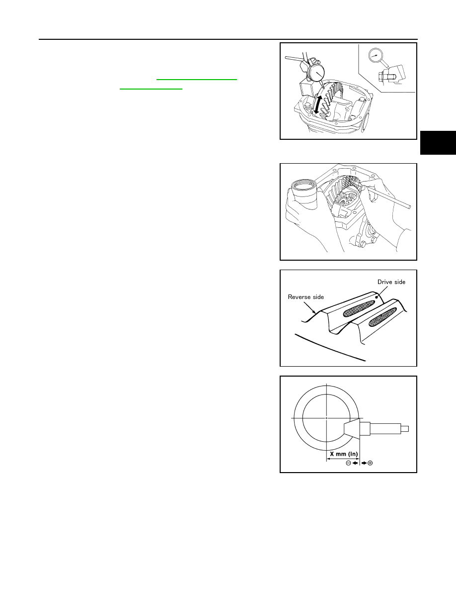
1. Fit a dial indicator to the drive gear back face.
2. Rotate the drive gear to measure runout.

• If the runout is outside of the limit, check the condition of the drive

gear assembly. Foreign material may be caught between the drive

gear and differential case, or the differential case or drive gear may

be deformed.

CAUTION:

Replace drive gear and drive pinion as a set.

Tooth Contact

1. Apply red lead to the drive gear.

NOTE:

Apply red lead to both faces of three to four gears, at four loca-

tions evenly spaced on the drive gear.

2. Rotate the drive gear back and forth several times. Then check

for correct drive pinion to drive gear tooth contact as shown.

CAUTION:

Check tooth contact on drive side and reverse side.

3. If the tooth contact is improperly adjusted, follow the procedure

below to adjust the pinion height (dimension X).

Runout limit

: Refer to 

DLN-270, "Inspection 

and Adjustment"

SPD886

SPD357

SDIA0570E

SDIA0517E

DLN-256

< DISASSEMBLY AND ASSEMBLY >

[REAR FINAL DRIVE: R230]

REAR FINAL DRIVE

• If the tooth contact is near the face (face contact), or near the heel

(heel contact), use a thicker drive pinion height adjusting washers

to move the drive pinion closer to the drive gear.

Refer to 

DLN-270, "Inspection and Adjustment"

.

• If the tooth contact is near the flank (flank contact), or near the toe

(toe contact), use a thinner drive pinion height adjusting washers to

move the drive pinion farther from the drive gear.

Refer to 

DLN-270, "Inspection and Adjustment"

.

Backlash

1. Fit a dial indicator to the drive gear face to measure the back-

lash.

• If the backlash is outside of the specification, change the thickness

of the side bearing adjusting washers.

CAUTION:

Do not change the total thickness of side bearing adjusting washers as it will change the side bearing

preload torque.

Companion Flange Runout

PDIA0440E

PDIA0441E

Backlash

: Refer to 

DLN-270, "Inspection and 

Adjustment"

If the backlash is greater than specification:

Make side bearing adjusting washer thicker on drive 
gear back side, and side bearing adjusting washer 
thinner on drive gear tooth side by the same amount. 
Refer to 

DLN-270, "Inspection and Adjustment"

.

If the backlash is less than specification:

Make side bearing adjusting washer thinner on drive 
gear back side, and side bearing adjusting washer 
thicker on drive gear tooth side by the same amount. 
Refer to 

DLN-270, "Inspection and Adjustment"

.

SPD513

REAR FINAL DRIVE

DLN-257

< DISASSEMBLY AND ASSEMBLY >

[REAR FINAL DRIVE: R230]

C

E

F

G

H

I

J

K

L

M

A

B

DLN

N

O

P

1. Rotate companion flange and check for runout on the outer face

of the companion flange using suitable tool.

2. If the runout is outside of the runout limit, follow the procedure

below to adjust.

a. Rotate the companion flange on the drive pinion by 90

°, 180°

and 270

° while checking for the position where the runout is

minimum.

b. If the runout is still outside of the runout limit after the companion

flange has been rotated on the drive pinion, possible cause could be an assembly malfunction of drive pin-

ion and drive pinion bearing or a malfunctioning drive pinion bearing.

c. If the runout is still outside of the runout limit after repair of the assembly of drive pinion and drive pinion

bearing or drive pinion bearing, replace the companion flange.

DISASSEMBLY

Side Flange

1. Drain the differential gear oil if necessary.
2. Remove the side flange using Tools.

3. Remove the side oil seal using suitable tool.

CAUTION:

Do not to damage gear carrier.

Differential Assembly

1. Remove the side flanges. 
2. Remove the carrier cover bolts.
3. Remove the carrier cover bolts and separate the carrier cover

from the gear carrier using Tool.

CAUTION:

• Do not damage the mating surface.

• Do not insert flat-bladed screwdriver, this will damage the

mating surface.

Runout limit

: Refer to 

DLN-270, "Inspection and 

Adjustment"

WDIA0231E

Tool numbers

A: KV40104100 ( — )
B: ST36230000 (J-25840-A)

WDIA0115E

LDIA0109E

Tool number

: KV10111100 (J-37228)

WDIA0123E

DLN-258

< DISASSEMBLY AND ASSEMBLY >

[REAR FINAL DRIVE: R230]

REAR FINAL DRIVE

4. Mount the carrier on the Tool using two 45 mm (1.77 in) spacers.

5. For proper reinstallation, paint matching marks on one side of

the side bearing cap and gear carrier.

CAUTION:

• For matching marks, use paint. Do not damage side bear-

ing cap or gear carrier.

• Side bearing caps are line-board during manufacture. The

matching marks are used to reinstall them in their original

positions.

6. Remove the side bearing caps.

7. Lift the differential case assembly out using Tool.

CAUTION:

Tool number

: KV38100800 (J-25604-01)

SPD888

SDIA1795E

S-PD343

Tool number

: HT72400000 ( — )

S-PD344


Content   ..  331  332  333  334   ..