Infiniti QX56 (JA60). Manual - part 288
P1828 LINE PRESSURE SWITCH
DLN-75
< COMPONENT DIAGNOSIS >
[ATX14B]
C
E
F
G
H
I
J
K
L
M
A
B
DLN
N
O
P
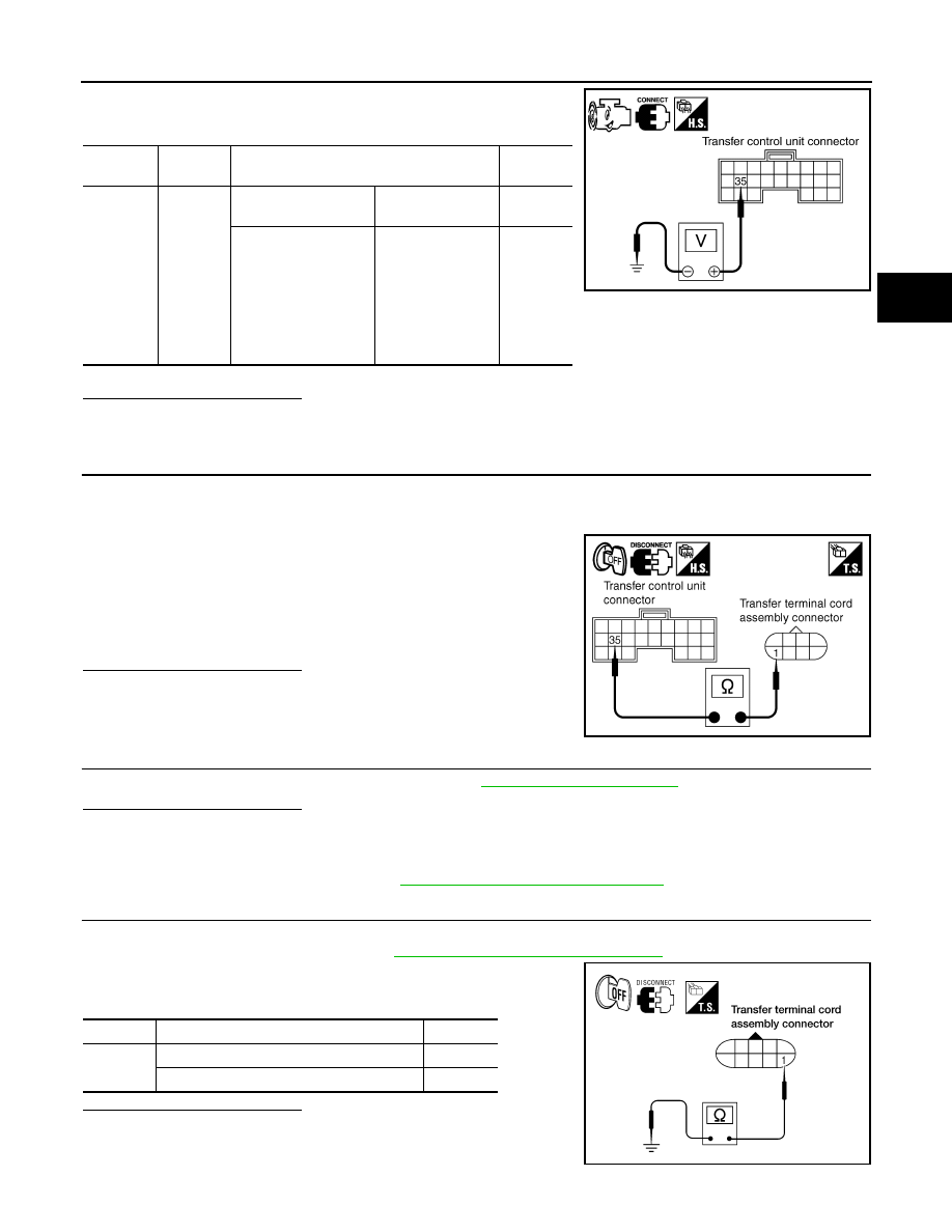
2. Check voltage between transfer control unit harness connector
terminals and ground.
Are inspection results normal?
YES
>> GO TO 5.
NO
>> GO TO 2.
2.
CHECK HARNESS BETWEEN TRANSFER CONTROL UNIT AND LINE PRESSURE SWITCH
1. Turn ignition switch OFF. (Stay for at least 5 seconds.)
2. Disconnect transfer control unit harness connector and the transfer terminal cord assembly harness con-
nector.
3. Check continuity between transfer control unit harness connec-
tor E143 terminal 35 and transfer terminal cord assembly har-
ness connector F56 terminal 1.
Also check harness for short to ground and short to power.
Are inspection results normal?
YES
>> GO TO 3.
NO
>> Repair or replace damaged parts.
3.
CHECK TRANSFER CONTROL UNIT
Check transfer control unit input/output signal. Refer to
Are inspection results normal?
YES
>> GO TO 4.
NO
>> Check the following. If any items are damaged, repair or replace damaged parts.
• Transfer control unit pin terminals for damage or loose connection with harness connector.
• Transfer control unit. Refer to
DLN-130, "Removal and Installation"
.
4.
CHECK LINE PRESSURE SWITCH
1. Turn ignition switch OFF. (Stay for at least 5 seconds.)
2. Remove line pressure switch. Refer to
DLN-16, "Component Parts Location"
.
3. Push and release line pressure switch and check continuity
between terminal 1 and ground.
Are inspection results normal?
YES
>> GO TO 5.
NO
>> Replace line pressure switch.
Connector
Terminal
Condition
Voltage
(Approx.)
E143
35 -
Ground
• A/T selector lever D
position
4WD shift switch:
AUTO
0V
• Except the above
• The vehicle has
been left at room
temperature for 5
minutes and more
with ignition switch
in OFF position.
• Ignition switch:
ON
• A/T selector le-
ver: P or N posi-
tion
• 4WD shift
switch: other
than AUTO
Battery
voltage
SDIA2751E
Continuity should exist.
SDIA2752E
Terminal
Condition
Continuity
1 -
Ground
Push line pressure switch
Yes
Release line pressure switch
No
WDIA0172E