Infiniti QX56 (JA60). Manual - part 284
P1823 2-4 SOLENOID
DLN-59
< COMPONENT DIAGNOSIS >
[ATX14B]
C
E
F
G
H
I
J
K
L
M
A
B
DLN
N
O
P
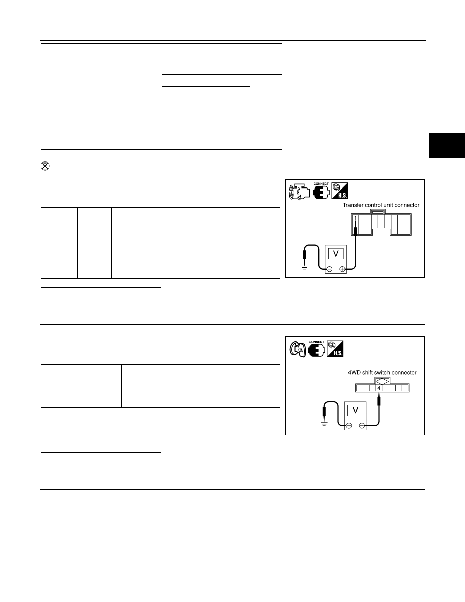
Without CONSULT-III
1. Start engine.
2. Check voltage between transfer control unit harness connector
terminal and ground.
Are the inspection results normal?
YES
>> GO TO 7.
NO
>> GO TO 3.
3.
CHECK 4WD SHIFT SWITCH SIGNAL
1. Turn ignition switch ON. (Do not start engine.)
2. Check voltage between transfer control unit harness connector
terminals and ground.
Are the inspection results normal?
YES
>> GO TO 4.
NO
>> Check 4WD shift switch. Refer to
DLN-34, "Component Inspection"
4.
CHECK HARNESS BETWEEN 4WD SHIFT SWITCH AND TRANSFER TERMINAL CORD ASSEMBLY
1. Turn ignition switch OFF. (Stay for at least 5 seconds.)
2. Disconnect 4WD shift switch harness connector and transfer terminal cord assembly harness connector.
2-4WD SOL
MON
• Vehicle stopped
• Engine running
• A/T selector lever N
position
• Brake pedal de-
pressed
4WD shift switch: 2WD
OFF
4WD shift switch: AUTO
ON
4WD shift switch: 4H
4WD shift switch: 4LO
4WD shift switch: AUTO
(Wait function is operating.)
OFF
4WD shift switch: 4H (Wait
function is operating.)
OFF
Monitored
item
Condition
Display
value
Connector
Terminal
Condition
Voltage
(Approx.)
E142
1 -
Ground
• Vehicle stopped
• Engine running
• A/T selector lever
N position
• Brake pedal de-
pressed
4WD shift switch: 2WD 0V
4WD shift switch: AU-
TO, 4H or 4LO
Battery
voltage
SDIA2728E
Connector
Terminal
Condition
Voltage (Ap-
prox.)
M141
4 - ground
4WD shift switch: AUTO, 4H or 4LO Battery voltage
4WD shift switch: 2WD
0V
SDIA2729E