Infiniti QX56 (JA60). Manual - part 279


  Index      Infiniti     Infiniti QX56 (JA60) - service repair manual 2010 year


Search            


Content   ..  277  278  279  280   ..


Infiniti QX56 (JA60). Manual - part 279


P1816 TRANSMISSION RANGE SWITCH

DLN-39

< COMPONENT DIAGNOSIS >

[ATX14B]

C

E

F

G

H

I

J

K

L

M

A

B

DLN

N

O

P

P1816 TRANSMISSION RANGE SWITCH

Description

INFOID:0000000005148800

The transmission range switch transmits the A/T position indicator signal (transmission range switch signal)

via CAN communication to the transfer control unit.  DTC P1816 will set when the transmission range switch

signal is malfunctioning or there is a communication error.

DTC Logic

INFOID:0000000005148801

DTC DETECTION LOGIC

DTC CONFIRMATION PROCEDURE

1.

DTC CONFIRMATION PROCEDURE

1. Turn ignition switch ON.

2. Perform self-diagnosis.
Is DTC P1816 displayed?

YES

>> Perform diagnosis procedure. Refer to 

DLN-39, "Diagnosis Procedure"

.

NO

>> Inspection End.

Diagnosis Procedure

INFOID:0000000005148802

1.

CHECK DTC WITH TCM

Perform self-diagnosis with TCM. Refer to 

TM-32, "CONSULT-III Function (TRANSMISSION)"

.

Is any malfunction detected by self-diagnosis?

YES

>> Check the malfunctioning system.

NO

>> GO TO 2.

2.

CHECK TRANSFER CONTROL UNIT

Check transfer control unit input/output signal. Refer to 

DLN-81, "Reference Value"

.

Are inspection results normal?

YES

>> GO TO 3.

NO

>> Check transfer control unit pin terminals for damage or loose connection with harness connector.

If any items are damaged, repair or replace damaged parts.

3.

CHECK DTC

Drive the vehicle and then perform self-diagnosis.
Are inspection results normal?

YES

>> Inspection End.

NO

>> Perform self-diagnosis with TCM again.
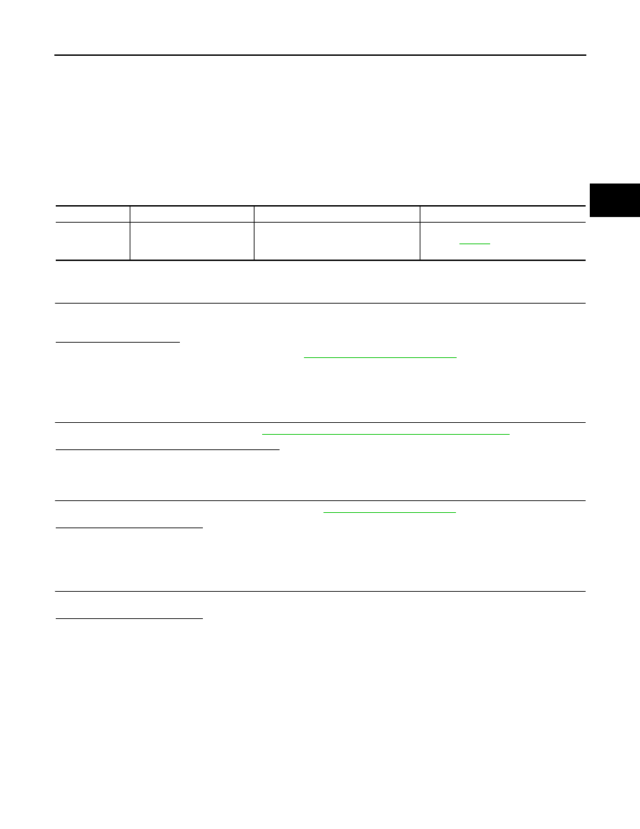
DTC

CONSULT-III

Diagnostic item is detected when...

Reference

[P1816]

PNP SW/CIRC

When transmission range switch signal 
is malfunctioning or communication er-
ror between the control units.

Refer to 

DLN-39

.

DLN-40

< COMPONENT DIAGNOSIS >

[ATX14B]

P1817 ACTUATOR MOTOR

P1817 ACTUATOR MOTOR

Description

INFOID:0000000005148803

The actuator motor receives signals from the transfer control unit and controls shift rods which shift the trans-

fer case.  DTC P1817 will set when any of the following occur:

• Motor does not operate properly due to open or short circuit in actuator motor.

• Malfunction is detected in the actuator motor. (When 4WD shift switch is operated and actuator motor does

not operate)

• Malfunction is detected in transfer shift high relay or transfer shift low relay.

DTC Logic

INFOID:0000000005148804

DTC DETECTION LOGIC

DTC CONFIRMATION PROCEDURE

1.

DTC CONFIRMATION PROCEDURE

1. Turn ignition switch ON.

2. Perform self-diagnosis.
Is DTC P1817 detected?

YES

>> Perform diagnosis procedure. Refer to 

DLN-40, "Diagnosis Procedure"

.

NO

>> Inspection End.

Diagnosis Procedure

INFOID:0000000005148805

Regarding Wiring Diagram information, refer to 

DLN-89, "Wiring Diagram - ALL-MODE 4WD SYSTEM -"

.

1.

CHECK ACTUATOR MOTOR SIGNAL

With CONSULT-III

1. Start engine.

2. Select DATA MONITOR mode for ALL MODE AWD/4WD with CONSULT-III.

3. Read out the value of SHIFT ACT1, SHIFT AC MON1, SHIFT ACT2 and SHIFT AC MON2.

DTC

CONSULT-III

Diagnostic item is detected when...

Reference

[P1817]

SHIFT ACTUATOR

• Motor does not operate properly due 

to open or short circuit in actuator mo-
tor.

• Malfunction is detected in the actuator 

motor. (When 4WD shift switch is op-
erated and actuator motor is not oper-
ated)

• Malfunction is detected in transfer shift 

high relay and transfer shift low relay.

Refer to 

DLN-40

.

Monitored 

item

Condition

Display 

value

SHIFT ACT1

• Vehicle stopped
• Engine running
• A/T selector lever N position
• Brake pedal depressed

4WD shift switch: 4H 
to 4LO (Wait function 
is operating.)

ON

Except the above

OFF

SHIFT AC 
MON1

• Vehicle stopped
• Engine running
• A/T selector lever N position
• Brake pedal depressed

4WD shift switch: 4H 
to 4LO (Wait function 
is operating.)

ON

Except the above

OFF

P1817 ACTUATOR MOTOR

DLN-41

< COMPONENT DIAGNOSIS >

[ATX14B]

C

E

F

G

H

I

J

K

L

M

A

B

DLN

N

O

P

Without CONSULT-III

1. Start engine.

2. Check voltage between transfer control unit harness connector

terminal and ground.

Are the inspection results normal?

YES 

>> GO TO 7.

NO

>> GO TO 2.

2.

CHECK ACTUATOR MOTOR POWER SUPPLY CIRCUIT

1. Turn ignition switch OFF. (Stay for at least 5 seconds.)

2. Remove transfer shift high relay and transfer shift low relay.

SHIFT ACT2

• Vehicle stopped
• Engine running
• A/T selector lever N position
• Brake pedal depressed

4WD shift switch: 
4LO to 4H (Wait func-
tion is operating.)

ON

Except the above

OFF

SHIFT AC 
MON2

• Vehicle stopped
• Engine running
• A/T selector lever N position
• Brake pedal depressed

4WD shift switch: 
4LO to 4H (Wait func-
tion is operating.)

ON

Except the above

OFF

Connector

Terminal

Condition

Voltage 

(Approx.)

E142

4 - 

Ground

• Vehicle stopped
• Engine running
• A/T selector lever 

N position

• Brake pedal de-

pressed

4WD shift switch: 4H to 
4LO (Wait function is 
operating.)

Battery 
voltage

Except the above

0V

13 - 

Ground

• Vehicle stopped
• Engine running
• A/T selector lever 

N position

• Brake pedal de-

pressed

4WD shift switch: 4LO 
to 4H (Wait function is 
operating.)

Battery 
voltage

Except the above

0V

E143

33 - 

Ground

• Vehicle stopped
• Engine running
• A/T selector lever 

N position

• Brake pedal de-

pressed

4WD shift switch: 4H to 
4LO (Wait function is 
operating.)

Battery 
voltage

Except the above

0V

42 - 

Ground

• Vehicle stopped
• Engine running
• A/T selector lever 

N position

• Brake pedal de-

pressed

4WD shift switch: 4LO 
to 4H (Wait function is 
operating.)

Battery 
voltage

Except the above

0V

Monitored 

item

Condition

Display 

value

SDIA2705E

DLN-42

< COMPONENT DIAGNOSIS >

[ATX14B]

P1817 ACTUATOR MOTOR

3. Check voltage between transfer shift high relay harness connec-

tor E46 terminal 5 (A), transfer shift low relay harness connector

E47 terminal 5 (B) and ground.

4. Turn ignition switch ON. (Do not start engine.)

5. Check voltage between transfer shift high relay harness connec-

tor E46 terminal 5 (A), transfer shift low relay harness connector

E47 terminal 5 (B) and ground.

Are the inspection results normal?

YES

>> GO TO 3.

NO

>> Check the following. If any items are damaged, repair or replace damaged parts.

• 20A fuse (No. 57, located in the fuse and relay box).

• Harness for short or open between battery, transfer shift high relay harness connector terminal 5

and transfer shift low relay harness connector terminal 5.

3.

CHECK ACTUATOR MOTOR GROUND CIRCUIT

1. Turn ignition switch OFF. (Stay for at least 5 seconds.)

2. Remove transfer shift high relay and transfer shift low relay. Refer to 

DLN-16, "Component Parts Loca-

tion"

.

3. Check continuity between transfer shift high relay harness con-

nector E46 terminals 2, 4 (A) and transfer shift low relay harness

connector E47 terminals 2, 4 (B) and ground.

Also check harness for short to ground and short to power.

Are the inspection results normal?

YES

>> GO TO 4.

NO

>> Repair open circuit or short to ground or short to power

in harness or connectors.

4.

CHECK TRANSFER SHIFT RELAY

1. Turn ignition switch OFF.

2. Remove transfer shift high relay and transfer shift low relay. Refer to 

DLN-16, "Component Parts Loca-

tion"

.

3. Apply 12V direct current between transfer shift relay terminals 1

and 2.

4. Check continuity between relay terminals 3 and 4, 3 and 5.

Connector

Terminal

Voltage (Approx.)

A: E46

5 - Ground

Battery voltage

B: E47

5 - Ground

WDIA0310E

Connector

Terminal

Voltage (Approx.)

A: E46

5 - Ground

Battery voltage

B: E47

5 - Ground

WDIA0311E

Continuity should exist.

WDIA0312E

Terminal

Condition

Continuity

3 - 4

12V direct current supply between terminals 1 and 2

No

OFF

Yes

3 - 5

12V direct current supply between terminals 1 and 2

Yes

OFF

No

WIIA0291E


Content   ..  277  278  279  280   ..