Infiniti QX56 (JA60). Manual - part 241
PINCH STRIP SYSTEM
DLK-135
< COMPONENT DIAGNOSIS >
[WITH INTELLIGENT KEY SYSTEM]
C
D
E
F
G
H
I
J
L
M
A
B
DLK
N
O
P
PINCH STRIP SYSTEM
Diagnosis Procedure
INFOID:0000000005147003
Regarding Wiring Diagram information, refer to
DLK-199, "Wiring Diagram—AUTOMATIC BACK DOOR SYS-
1.
PINCH STRIP SIGNAL INSPECTION
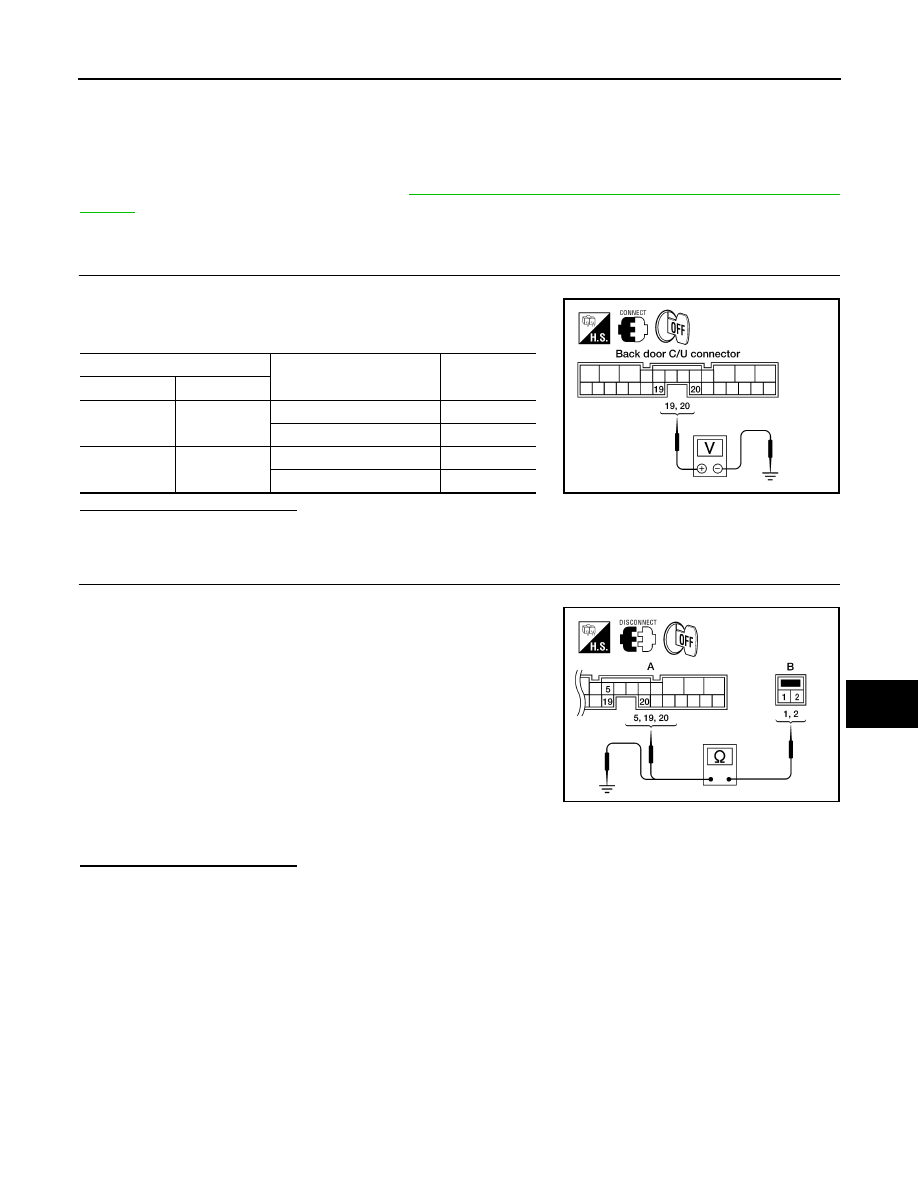
1. Turn ignition switch OFF.
2. While operating the pinch strip, check voltage between back
door control unit connector B55 terminals 19, 20 and ground.
Is the inspection result normal?
YES
>> Switch is OK.
NO
>> GO TO 2
2.
PINCH STRIP CIRCUIT INSPECTION
1. Disconnect pinch strip and back door control unit connector.
2. Check continuity between back door control unit connector (A)
B55 terminals 5, 19 (RH) or 5, 20 (LH) and pinch strip connector
(B) D715 (RH), D517 (LH) terminals 1, 2.
3. Check continuity between pinch strip connector (B) D715 (RH),
D517 (LH) terminals 1, 2 and ground.
Is the inspection result normal?
YES
>> Replace the pinch strip.
NO
>> Repair the harness between the pinch strip and the back door control unit.
Terminals
Measuring condition
Voltage (V)
(Approx.)
(+)
(-)
19
Ground
Pinch strip RH operation
0
Other
4
20
Ground
Pinch strip LH operation
0
Other
4
LIIA0811E
RH: 1 - 19
: Continuity should exist.
LH: 1 - 20
: Continuity should exist.
RH and LH 2 - 5 : Continuity should exist.
1 - Ground
: Continuity should not exist.
2 - Ground
: Continuity should not exist.
ALKIA0672ZZ