Infiniti QX56 (JA60). Manual - part 207
 

  Index      Infiniti     Infiniti QX56 (JA60) - service repair manual 2010 year


Search            


Content   ..  205  206  207  208   ..


Infiniti QX56 (JA60). Manual - part 207


REAR WINDOW DEFOGGER

DEF-45

< ON-VEHICLE REPAIR >

C

D

E

F

G

H

I

J

K

M

A

B

DEF

N

O

P

ON-VEHICLE REPAIR

REAR WINDOW DEFOGGER

Filament Check

INFOID:0000000005146857

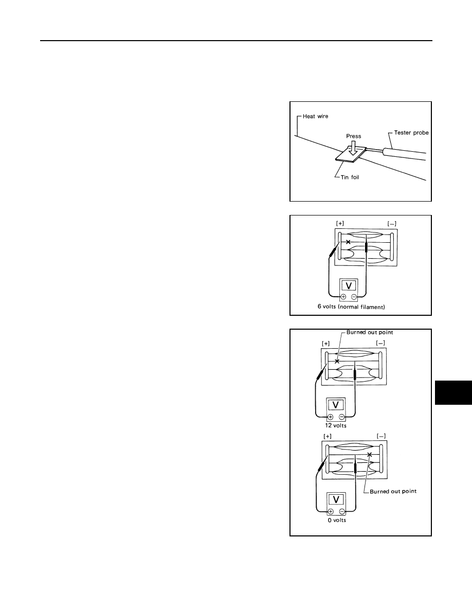
1. When measuring voltage, wrap tin foil around the top of the neg-

ative probe.Then press the foil against the wire with your finger.

2. Attach probe circuit tester (in Volt range) to middle portion of

each filament.

3. If a filament is burned out, circuit tester registers 0 or battery

voltage.

4. To locate burned out point, move probe to left and right along fil-

ament. Test needle will swing abruptly when probe passes the

point.

Filament Repair

INFOID:0000000005146858

REPAIR EQUIPMENT

• Conductive silver composition (DuPont No. 4817 or equivalent)

• Ruler 30 cm (11.8 in) long

SEL122R

SEL263

SEL265

DEF-46

< ON-VEHICLE REPAIR >

REAR WINDOW DEFOGGER

• Drawing pen

• Heat gun

• Alcohol

• Cloth

REPAIRING PROCEDURE

1. Wipe broken heat wire and its surrounding area clean with a

cloth dampened in alcohol.

2. Apply a small amount of conductive silver composition to tip of

drawing pen.

Shake silver composition container before use.

3. Place ruler on glass along broken line. Deposit conductive silver

composition on break with drawing pen. Slightly overlap existing

heat wire on both sides [preferably 5 mm (0.20 in)] of the break.

4. After repair has been completed, check repaired wire for conti-

nuity. This check should be conducted 10 minutes after silver

composition is deposited.

Do not touch repaired area while test is being conducted.

5. Apply a constant stream of hot air directly to the repaired area

for approximately 20 minutes with a heat gun. A minimum dis-

tance of 3 cm (1.2 in) should be kept between repaired area and

hot air outlet.

If a heat gun is not available, let the repaired area dry for 24

hours.

PIIA0215E

SEL012D

SEL013D

DLK-1

BODY EXTERIOR, DOORS, ROOF & VEHICLE SECURITY

C

D

E

F

G

H

I

J

L

M

SECTION 

DLK

A

B

DLK

N

O

P

CONTENTS

DOOR & LOCK

WITH INTELLIGENT KEY SYSTEM

BASIC INSPECTION  ....................................

6

DIAGNOSIS AND REPAIR WORKFLOW  ..........

6

Work Flow  .................................................................

6

INSPECTION AND ADJUSTMENT .....................

9

ADDITIONAL SERVICE WHEN REMOVING BAT-
TERY NEGATIVE TERMINAL ...................................
..

9

ADDITIONAL SERVICE WHEN REMOVING 
BATTERY NEGATIVE TERMINAL : Description ......

9

ADDITIONAL SERVICE WHEN REMOVING 
BATTERY NEGATIVE TERMINAL : Special Re-
pair Requirement .....................................................
..

9

ADDITIONAL SERVICE WHEN REPLACING 
CONTROL UNIT  ........................................................
..

9

ADDITIONAL SERVICE WHEN REPLACING 
CONTROL UNIT : Description  ................................
..

9

ADDITIONAL SERVICE WHEN REPLACING 
CONTROL UNIT : Special Repair Requirement  .....
..

9

FUNCTION DIAGNOSIS ..............................

10

AUTOMATIC DOOR LOCKS  .............................

10

System Diagram ......................................................

10

System Description  .................................................

10

Component Parts Location ....................................

12

Component Description ..........................................

12

DOOR LOCK FUNCTION  ..................................

14

DOOR LOCK AND UNLOCK SWITCH  .....................

14

DOOR LOCK AND UNLOCK SWITCH : System 
Diagram ...................................................................

14

DOOR LOCK AND UNLOCK SWITCH : System 
Description ..............................................................

14

DOOR LOCK AND UNLOCK SWITCH : 
Component Parts Location ....................................

15

DOOR LOCK AND UNLOCK SWITCH : 
Component Description ..........................................

15

DOOR REQUEST SWITCH  .......................................

16

DOOR REQUEST SWITCH : System Diagram .......

16

DOOR REQUEST SWITCH : System Description ....

16

DOOR REQUEST SWITCH : 
Component Parts Location ....................................

19

DOOR REQUEST SWITCH : 
Component Description ..........................................

21

INTELLIGENT KEY ....................................................

21

INTELLIGENT KEY : System Diagram ....................

21

INTELLIGENT KEY : System Description ...............

21

INTELLIGENT KEY : Component Parts Location ....

24

INTELLIGENT KEY : Component Description ........

25

BACK DOOR OPENER FUNCTION .................

27

BACK DOOR OPENER SWITCH  ..............................

27

BACK DOOR OPENER SWITCH : System Dia-
gram ........................................................................

27

BACK DOOR OPENER SWITCH : System De-
scription ...................................................................

27

BACK DOOR OPENER SWITCH : 
Component Parts Location ....................................

32

BACK DOOR OPENER SWITCH : 
Component Description ..........................................

32

INTELLIGENT KEY ....................................................

33

INTELLIGENT KEY : System Diagram ....................

33

INTELLIGENT KEY : System Description ...............

33

INTELLIGENT KEY : Component Parts Location ....

35

INTELLIGENT KEY : Component Description ........

36

WARNING FUNCTION ......................................

38

System Description ..................................................

38

Component Parts Location ....................................

42

KEY REMINDER FUNCTION ............................

44

System Description ..................................................

44

Component Parts Location ....................................

45

HAZARD AND BUZZER REMINDER FUNC-
TION ..................................................................

47

DLK-2

System Diagram  .....................................................

47

System Description .................................................

47

Component Parts Location ...................................

48

Component Description .........................................

50

HOMELINK UNIVERSAL TRANSCEIVER ........

51

Component Description  ..........................................

51

DIAGNOSIS SYSTEM (BCM) ............................

52

COMMON ITEM  ........................................................

52

COMMON ITEM : CONSULT-III Function (BCM - 
COMMON ITEM)  ...................................................
.

52

DOOR LOCK .............................................................

52

DOOR LOCK : CONSULT-III Function (BCM - 
DOOR LOCK) ........................................................
.

53

MULTIREMOTE ENT  ................................................

53

MULTIREMOTE ENT : CONSULT-III Function 
(BCM - MULTIREMOTE ENT) ...............................
.

53

INTELLIGENT KEY ...................................................

55

INTELLIGENT KEY : CONSULT-III Function 
(BCM - INTELLIGENT KEY) ..................................
.

55

DIAGNOSIS SYSTEM (INTELLIGENT KEY 
UNIT) ..................................................................

56

CONSULT-III Function (INTELLIGENT KEY) .........

56

COMPONENT DIAGNOSIS  ........................

58

U1000 CAN COMM CIRCUIT  ............................

58

Description ..............................................................

58

DTC Logic ...............................................................

58

Diagnosis Procedure  ..............................................

58

U1010 CONTROL UNIT (CAN)  .........................

59

DTC Logic ...............................................................

59

Diagnosis Procedure  ..............................................

59

Special Repair Requirement ...................................

59

CENTER CONSOLE AREA ANTENNA 
(REAR) ...............................................................

60

Description ..............................................................

60

Component Function Check .................................

60

Diagnosis Procedure  ..............................................

60

LUGGAGE AREA ANTENNA  ...........................

62

Description ..............................................................

62

Component Function Check .................................

62

Diagnosis Procedure  ..............................................

62

CENTER CONSOLE AREA ANTENNA 
(FRONT) .............................................................

64

Description ..............................................................

64

Component Function Check .................................

64

Diagnosis Procedure  ..............................................

64

OVERHEAD CONSOLE AREA ANTENNA  ......

66

Description ..............................................................

66

Component Function Check .................................

66

Diagnosis Procedure ...............................................

66

POWER SUPPLY AND GROUND CIRCUIT .....

68

INTELLIGENT KEY UNIT ..........................................

68

INTELLIGENT KEY UNIT : Diagnosis Procedure ...

68

BCM (BODY CONTROL MODULE) ..........................

68

BCM (BODY CONTROL MODULE) : Diagnosis 
Procedure ...............................................................

68

BACK DOOR CONTROL UNIT .................................

69

BACK DOOR CONTROL UNIT : Diagnosis Proce-
dure .........................................................................

69

DOOR SWITCH  .................................................

71

Description ..............................................................

71

Component Function Check ..................................

71

Diagnosis Procedure ...............................................

71

DOOR LOCK AND UNLOCK SWITCH .............

74

DRIVER SIDE  ............................................................

74

DRIVER SIDE : Description  ....................................

74

DRIVER SIDE : Component Function Check ........

74

DRIVER SIDE : Diagnosis Procedure .....................

74

PASSENGER SIDE  ...................................................

76

PASSENGER SIDE : Description ...........................

76

PASSENGER SIDE : 
Component Function Check ..................................

76

PASSENGER SIDE : Diagnosis Procedure ............

76

KEY CYLINDER SWITCH  .................................

79

Description ..............................................................

79

Component Function Check  ...................................

79

Diagnosis Procedure ...............................................

79

FRONT DOOR LOCK ACTUATOR LH (DOOR 
UNLOCK SENSOR)  ..........................................

81

Description ..............................................................

81

Component Function Check ..................................

81

Diagnosis Procedure ...............................................

81

Component Inspection  ............................................

82

DOOR REQUEST SWITCH ...............................

83

Description ..............................................................

83

Component Function Check ..................................

83

Diagnosis Procedure ...............................................

83

Component Inspection  ............................................

85

DOOR LOCK ACTUATOR  ................................

86

DRIVER SIDE  ............................................................

86

DRIVER SIDE : Description  ....................................

86

DRIVER SIDE : Component Function Check ........

86

DRIVER SIDE : Diagnosis Procedure .....................

86

PASSENGER SIDE  ...................................................

87

PASSENGER SIDE : Description ...........................

87

PASSENGER SIDE : 
Component Function Check ..................................

87

PASSENGER SIDE : Diagnosis Procedure ............

87


Content   ..  205  206  207  208   ..