Infiniti QX56 (JA60). Manual - part 150


  Index      Infiniti     Infiniti QX56 (JA60) - service repair manual 2010 year


Search            


Content   ..  148  149  150  151   ..


Infiniti QX56 (JA60). Manual - part 150


PREPARATION

BRC-113

< PREPARATION >

[VDC/TCS/ABS]

C

D

E

G

H

I

J

K

L

M

A

B

BRC

N

O

P

PREPARATION

PREPARATION

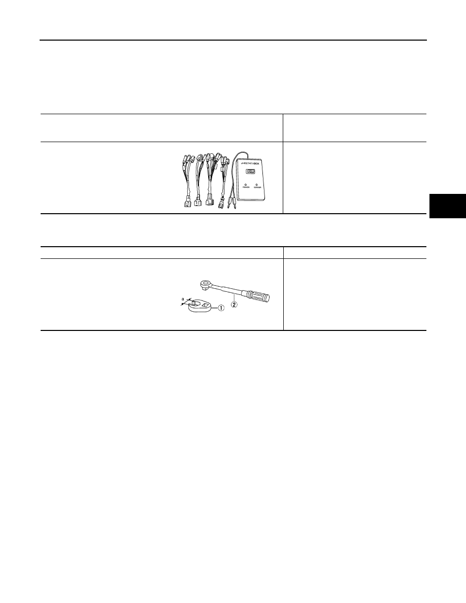
Special Service Tool

INFOID:0000000005148097

The actual shapes of Kent-Moore tools may differ from those of special service tools illustrated here.

Commercial Service Tool

INFOID:0000000005148098

Tool number
(Kent-Moore No.)
Tool name

Description

KV991J0080
(J-45741)
ABS active wheel sensor tester

Checking operation of ABS active wheel sen-
sors

WFIA0101E

Tool name

Description

1. Flare nut crowfoot
2. Torque wrench

Removing and installing brake piping
a: 10 mm (0.39 in)/12 mm (0.47 in)

S-NT360

BRC-114

< REMOVAL AND INSTALLATION >

[VDC/TCS/ABS]

WHEEL SENSORS

REMOVAL AND INSTALLATION

WHEEL SENSORS

Removal and Installation

INFOID:0000000005148099

REMOVAL

1. Remove wheel sensor bolt.

• When removing the front wheel sensor, first remove the disc rotor to gain access to the front wheel sen-

sor bolt. Refer to 

BR-31, "Removal and Installation of Brake Caliper and Rotor"

.

• When removing the rear wheel sensor, first remove the rear hub and bearing assembly to gain access to

the rear wheel sensor bolt. Refer to 

RAX-8, "Removal and Installation"

.

2. Pull out the sensor, being careful to turn it as little as possible.

CAUTION:

• Do not pull on the sensor harness.

3. Disconnect wheel sensor harness electrical connector, then remove harness from attaching points.

INSTALLATION

Installation is in the reverse order of removal. Tighten wheel sensor bolt to specification.

CAUTION:

• Inspect wheel sensor O-ring, replace sensor assembly if damaged.

• Before installing wheel sensor, make sure no foreign materials (such as iron fragments) are adhered

to the pick-up part of the sensor, to the inside of the sensor hole or on the rotor mating surface.

• Apply a coat of suitable grease to the wheel sensor O-ring and hole. Refer to 

MA-13, "Fluids and

Lubricants"

.

WFIA0376E

SENSOR ROTOR

BRC-115

< REMOVAL AND INSTALLATION >

[VDC/TCS/ABS]

C

D

E

G

H

I

J

K

L

M

A

B

BRC

N

O

P

SENSOR ROTOR

Removal and Installation

INFOID:0000000005148100

NOTE:

The wheel sensor rotors are built into the wheel hubs and are not removable. If damaged, replace wheel hub

and bearing assembly. Refer to 

FAX-7, "Removal and Installation"

 (front), 

RAX-8, "Removal and Installation"

(rear).

BRC-116

< REMOVAL AND INSTALLATION >

[VDC/TCS/ABS]

ACTUATOR AND ELECTRIC UNIT (ASSEMBLY)

ACTUATOR AND ELECTRIC UNIT (ASSEMBLY)

Removal and Installation

INFOID:0000000005148101

REMOVAL

1. Disconnect the battery negative terminal. Refer to 

PG-74, "Removal and Installation"

.

2. Remove the air cleaner and air duct assembly. Refer to 

EM-25, "Removal and Installation"

.

3. Drain the brake fluid. Refer to 

BR-17, "Drain and Refill"

.

4. Disconnect the actuator harness connector from the ABS actuator and electric unit (control unit).

CAUTION:

• To remove the brake tubes, use a flare nut wrench to prevent the flare nuts and brake tubes from

being damaged.

• Be careful not to splash brake fluid on painted areas; it may cause paint damage. If brake fluid is

splashed on painted areas, wash it away with water immediately.

5. Disconnect the brake tubes.
6. Remove the three bolts and remove the ABS actuator and electric unit (control unit).

INSTALLATION

Installation is in the reverse order of removal.

CAUTION:

• To install, use a flare nut crowfoot and torque wrench (commercial service tools).

1.

To rear left caliper
16.2 N·m (1.7 kg-m, 12 ft-lb)

2.

To rear right caliper
16.2 N·m (1.7 kg-m, 12 ft-lb)

3.

To front left caliper
16.2 N·m (1.7 kg-m, 12 ft-lb)

4.

To front right caliper
16.2 N·m (1.7 kg-m, 12 ft-lb)

5.

From the master cylinder secondary side
18.2 N·m (1.9 kg-m, 13 ft-lb)

6.

From the master cylinder primary side
18.2 N·m (1.9 kg-m, 13 ft-lb)

7.

ABS actuator and electric unit 
(control unit)

8.

Actuator harness connector

WFIA0375E


Content   ..  148  149  150  151   ..