Infiniti QX56 (JA60). Manual - part 127


  Index      Infiniti     Infiniti QX56 (JA60) - service repair manual 2010 year


Search            


Content   ..  125  126  127  128   ..


Infiniti QX56 (JA60). Manual - part 127


EBD

BRC-21

< FUNCTION DIAGNOSIS >

[VDC/TCS/ABS]

C

D

E

G

H

I

J

K

L

M

A

B

BRC

N

O

P

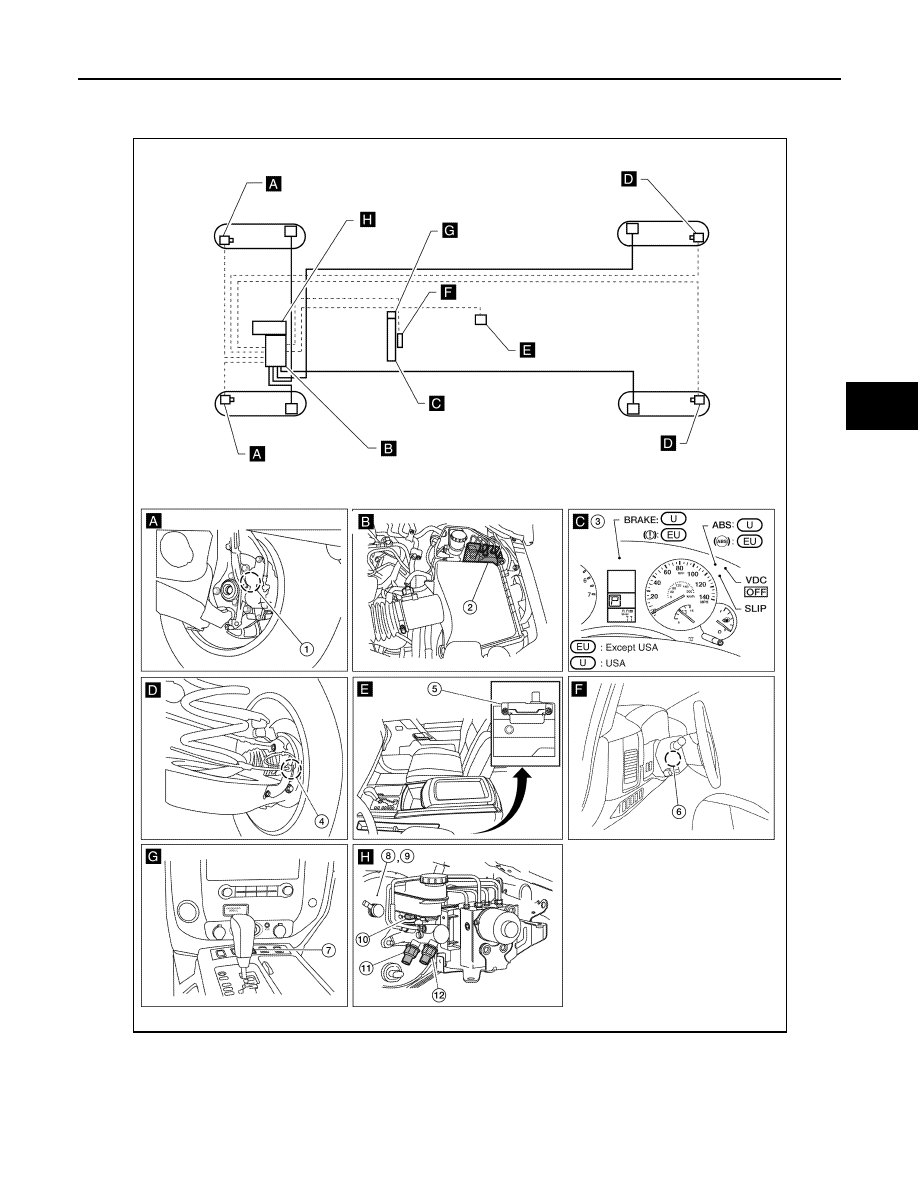
Component Parts Location

INFOID:0000000005206967

1.

Front wheel sensor LH E18
Front wheel sensor RH E117

2.

ABS actuator and electric unit (con-
trol unit) E125

3.

Combination meter M23, M24

4.

Rear wheel sensor LH C11
Rear wheel sensor RH C10

5.

Yaw rate/side/decel G sensor M108 6.

Steering angle sensor M17

AWFIA0572GB

BRC-22

< FUNCTION DIAGNOSIS >

[VDC/TCS/ABS]

EBD

Component Description

INFOID:0000000005206968

7.

VDC OFF switch M253

8.

Active booster E49

9.

Delta stroke sensor E114

10. Brake fluid level switch E21

11. Front pressure sensor E31

12. Rear pressure sensor E32

Component parts

Reference

ABS actuator and electric unit (control unit)

Pump

BRC-37, "Description"

Motor

Actuator relay

BRC-55, "Description"

Solenoid valve

BRC-47, "Description"

Wheel sensor

BRC-28, "Description"

ABS warning lamp

BRC-82, "Description"

Brake warning lamp

BRC-83, "Description"

DIAGNOSIS SYSTEM [ABS ACTUATOR AND ELECTRIC UNIT (CONTROL 

UNIT)]

BRC-23

< FUNCTION DIAGNOSIS >

[VDC/TCS/ABS]

C

D

E

G

H

I

J

K

L

M

A

B

BRC

N

O

P

DIAGNOSIS SYSTEM [ABS ACTUATOR AND ELECTRIC UNIT (CONTROL
UNIT)]

CONSULT-III Function (ABS)

INFOID:0000000005147962

FUNCTION

CONSULT-III can display each diagnostic item using the diagnostic test modes shown following.

SELF DIAGNOSTIC RESULT MODE

Operation Procedure

1. Before performing the self-diagnosis, start engine and drive vehicle at 30 km/h (19 MPH) or more for

approximately 1 minute.

How to Erase Self-diagnosis Results

1. After erasing DTC memory, start engine and drive vehicle at 30 km/h (19 MPH) or more for approximately

1 minute as the final inspection, and make sure that the ABS warning lamp, VDC OFF indicator lamp,

SLIP indicator lamp and brake warning lamp turn OFF.

CAUTION:

If memory cannot be erased, perform applicable diagnosis.

NOTE:

• When the wheel sensor malfunctions, after inspecting the wheel sensor system, the ABS warning lamp,

VDC OFF indicator lamp, SLIP indicator lamp and brake warning lamp will not turn OFF even when the

system is normal unless the vehicle is driving at approximately 30 km/h (19 MPH) or more for approxi-

mately 1 minute.

• Brake warning lamp will turn ON in case of parking brake operation (when switch is ON) or of brake fluid

level switch operation (when brake fluid is insufficient).

• VDC OFF switch should not stay “ON” position.

Display Item List

Refer to 

BRC-100, "DTC No. Index"

.

DATA MONITOR MODE

Display Item List

Diagnostic test mode

Function

Work support

This mode enables a technician to adjust some devices faster and more accurately by following 
the indications on CONSULT-III.

Data Monitor

Input/Output data in the ABS actuator and electric unit (control unit) can be read.

Active Test

Diagnostic test mode is which CONSULT-III drives some actuators apart from the ABS actuator 
and electric unit (control unit) and also shifts some parameters in a specified range.

Self Diagnostic Result

Self-diagnostic results can be read and erased quickly.

CAN diag support monitor

The results of transmit/receive diagnosis of CAN communication can be read.

ECU Identification

ABS actuator and electric unit (control unit) part number can be read.

Item

(Unit)

Data monitor item selection

Remarks

ECU INPUT

SIGNALS

MAIN

SIGNALS

SELECTION

FROM MENU

FR LH SENSOR 
 (km/h, mph)

×

×

×

Wheel speed (km/h, mph) calculated by front LH 
wheel sensor signal is displayed.

FR RH SENSOR 
 (km/h, mph)

×

×

×

Wheel speed (km/h, mph) calculated by front RH 
wheel sensor signal is displayed.

RR LH SENSOR 
 (km/h, mph)

×

×

×

Wheel speed (km/h, mph) calculated by rear LH 
wheel sensor signal is displayed.

RR RH SENSOR
 (km/h, mph)

×

×

×

Wheel speed (km/h, mph) calculated by rear RH 
wheel sensor signal is displayed.

BRC-24

< FUNCTION DIAGNOSIS >

[VDC/TCS/ABS]

DIAGNOSIS SYSTEM [ABS ACTUATOR AND ELECTRIC UNIT (CONTROL 

UNIT)]

DECEL G-SEN
 (G)

×

×

×

Longitudinal acceleration (G) detected by decel G-
sensor is displayed. 

FR RH IN SOL
(On/Off)

×

×

Front RH IN ABS solenoid (On/Off) status is dis-
played.

FR RH OUT SOL
(On/Off)

×

×

Front RH OUT ABS solenoid (On/Off) status is dis-
played.

FR LH IN SOL
(On/Off)

×

×

Front LH IN ABS solenoid (On/Off) status is displayed.

FR LH OUT SOL
(On/Off)

×

×

Front LH OUT ABS solenoid (On/Off) status is dis-
played.

RR RH IN SOL
(On/Off)

×

×

Rear RH IN ABS solenoid (On/Off) status is displayed.

RR RH OUT SOL
(On/Off) 

×

×

Rear RH OUT ABS solenoid (On/Off) status is dis-
played.

RR LH IN SOL
(On/Off)

×

×

Rear LH IN ABS solenoid (On/Off) status is displayed.

RR LH OUT SOL
(On/Off)

×

×

Rear LH OUT ABS solenoid (On/Off) status is dis-
played.

EBD WARN LAMP
(On/Off)

×

Brake warning lamp (On/Off) status is displayed.

STOP LAMP SW
(On/Off)

×

×

×

Stop lamp switch (On/Off) status is displayed.

MOTOR RELAY
(On/Off)

×

×

ABS motor relay signal (On/Off) status is displayed.

ACTUATOR RLY
(On/Off)

×

×

ABS actuator relay signal (On/Off) status is displayed.

ABS WARN LAMP
(On/Off)

×

×

ABS warning lamp (On/Off) status is displayed.

OFF LAMP
(On/Off)

×

×

VDC OFF Lamp (On/Off) status is displayed.

OFF  SW
(On/Off)

×

×

×

VDC OFF switch (On/Off) status is displayed.

SLIP LAMP
(On/Off)

×

×

SLIP indicator lamp (On/Off) status is displayed.

BATTERY VOLT
(V)

×

×

×

Voltage (V) supplied to ABS actuator and electric unit 
(control unit) is displayed.

GEAR
(1, 2, 3, 4, 5)

×

×

×

Gear position (1, 2, 3, 4, 5) judged by transmission 
range switch signal is displayed.

SLCT LVR POSI
(P, N, D)

×

×

×

Shift position (P, N, D) judged by transmission range 
switch signal.

ENGINE SPEED
(rpm)

×

×

×

Engine speed (rpm) judged by CAN communication 
signal is displayed.

YAW RATE SEN
(d/s)

×

×

×

Yaw rate (d/s) detected by yaw rate sensor is dis-
played.

R POSI SIG
(On/Off)

×

Reverse shift position (On/Off) judged by PNP switch 
signal.

4WD FAIL REQ
(On/Off)

×

Transfer control unit fail-safe mode (On/Off) is dis-
played.

N POSI SIG
(On/Off)

×

Shift position judged by transmission range switch 
signal.

Item

(Unit)

Data monitor item selection

Remarks

ECU INPUT

SIGNALS

MAIN

SIGNALS

SELECTION

FROM MENU


Content   ..  125  126  127  128   ..