Infiniti QX56 (JA60). Manual - part 115


  Index      Infiniti     Infiniti QX56 (JA60) - service repair manual 2010 year


Search            


Content   ..  113  114  115  116   ..


Infiniti QX56 (JA60). Manual - part 115


BR-20

< ON-VEHICLE REPAIR >

BRAKE PEDAL

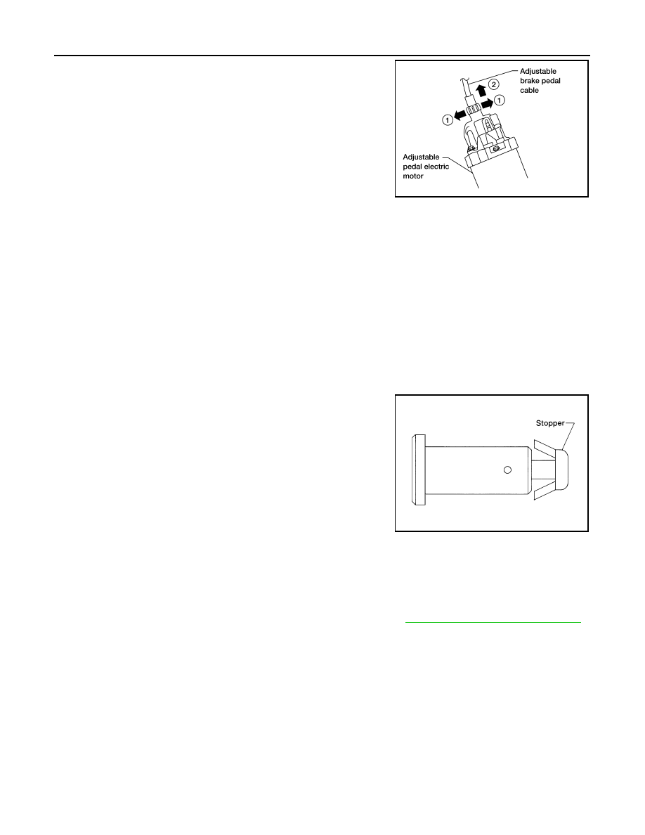
3. Disconnect the adjustable brake pedal cable from the adjustable

pedal electric motor.

• Unlock (1) then pull (2) the adjustable brake pedal cable to dis-

connect it from the adjustable pedal electric motor as shown.

4. Remove snap pin and clevis pin from the clevis of brake booster.
5. Remove brake pedal assembly nuts and remove the brake pedal assembly.

• Temporarily install the brake pedal assembly nuts by hand to support the brake booster.

WARNING:

Do not bend the brake tubing.

CAUTION:

• Before removal and installation, the accelerator and brake pedals must be in the forward most

position (closest to the floor). This is to align the base position of the accelerator and brake ped-

als.

• Do not disassemble the brake pedal adjusting mechanism.

• Avoid damage from dropping the brake pedal assembly during handling.

• Keep the brake pedal assembly away from water.

INSPECTION AFTER REMOVAL

Check the brake pedal assembly for the following items:

• Crack or deformation of clevis pin stopper

• Clevis pin deformation

• Crack of any welded portion of the brake pedal assembly

• Brake pedal bend or deformation

INSTALLATION

Installation is in the reverse order of removal.

• Check the brake pedal for smooth operation. There should be no binding or sticking when applying or

releasing the brake pedal.

• Check the brake pedal adjustable feature for smooth operation. There should be no binding or sticking when

adjusting the brake pedal forward or backward.

• After installing the brake pedal assembly, be sure to adjust it. Refer to 

BR-15, "Inspection and Adjustment"

.

LBIA0374E

SBR997

BRAKE TUBE AND HOSE

BR-21

< ON-VEHICLE REPAIR >

C

D

E

G

H

I

J

K

L

M

A

B

BR

N

O

P

BRAKE TUBE AND HOSE

Hydraulic Circuit

INFOID:0000000005147905

CAUTION:

• All hoses and piping (tubes) must be free from excessive bending, twisting and pulling.

• Make sure there is no interference with other parts when turning the steering wheel both clockwise

and counterclockwise.

• The brake piping is an important safety part. If a brake fluid leak is detected, always disassemble the

parts. Replace applicable part with a new one, if necessary.

• Be careful not to splash brake fluid on painted areas; it may cause paint damage. If brake fluid is

splashed on painted areas, wash it away with water immediately.

• Do not bend or twist brake hose sharply, or strongly pull it.

• When removing components, cover connections so that no dirt, dust, or other foreign matter gets in.

• Refill with new specified brake fluid. Refer to 

MA-13, "Fluids and Lubricants"

.

• Do not reuse drained brake fluid.

Removal and Installation of Front Brake Piping and Brake Hose

INFOID:0000000005147906

REMOVAL

1. Remove front wheel and tire using power tool. 
2. Remove brake reservoir cap.

1.

Actuator

2.

Master cylinder

3.

Brake booster

4.

Connector

A.

Union bolt
18.2 N·m (1.9 kg-m, 13 ft-lb)

B.

Flare nut M12
18.2 N·m (1.9 kg-m, 13 ft-lb)

C.

Flare nut M10
16.2 N·m (1.7 kg-m, 12 ft-lb)

AWFIA0411ZZ

BR-22

< ON-VEHICLE REPAIR >

BRAKE TUBE AND HOSE

3. Remove brake tube from brake hose, using a suitable tool.
4. Remove lock plate and brake hose from bracket.

5. Remove union bolt and then remove brake hose from cylinder

body.

INSTALLATION

1. Install brake hose by aligning with the protrusion on cylinder

body, then install the union bolt and new copper washers and

tighten to specification. Refer to 

BR-13, "Hydraulic Circuit"

.

CAUTION:

Do not reuse copper washer.

2. Insert brake hose end through bracket, then secure it to bracket

with lock plate.

3. Install brake tube to brake hose, then tighten the flare nut using

a suitable tool. Refer to 

BR-13, "Hydraulic Circuit"

.

4. Refill brake fluid and bleed air. Refer to 

BR-17, "Drain and Refill"

.

5. Install front wheel and tire using power tool. Refer to 

WT-49, "Rotation"

.

Removal and Installation of Rear Brake Piping and Brake Hose

INFOID:0000000005147907

REMOVAL

1. Remove rear wheel and tire using power tool.
2. Remove brake reservoir cap.

LFIA0213E

LFIA0214E

SFIA1137E

LFIA0213E

BRAKE TUBE AND HOSE

BR-23

< ON-VEHICLE REPAIR >

C

D

E

G

H

I

J

K

L

M

A

B

BR

N

O

P

3. Remove brake tube from brake hose, using a suitable tool.
4. Remove lock plate and brake hose from bracket.

5. Remove union bolt and then remove brake hose from cylinder

body.

INSTALLATION

1. Install brake hose by aligning with the protrusion on cylinder

body, then install the union bolt and new copper washers and

tighten to specification. Refer to 

BR-13, "Hydraulic Circuit"

.

CAUTION:

Do not reuse copper washer.

2. Insert brake hose end through bracket, then secure it to bracket

with lock plate.

3. Install brake tube to brake hose, then tighten the flare nut using

a suitable tool. Refer to 

BR-13, "Hydraulic Circuit"

.

4. Refill brake fluid and bleed air. Refer to 

BR-17, "Bleeding Brake System"

.

5. Install rear wheel and tire using power tool. Refer to 

WT-49, "Rotation"

.

Inspection After Installation

INFOID:0000000005147908

CAUTION:

Brake tubes and hoses are important safety parts. Always disassemble the parts and retighten their fit-

tings, if a brake fluid leak is detected. Replace applicable part with a new one, if a damaged part is

detected.

LFIA0213E

LFIA0212E

SFIA1137E

LFIA0213E


Content   ..  113  114  115  116   ..