Infiniti QX56 (JA60). Manual - part 104
BCS
COMBINATION SWITCH INPUT CIRCUIT
BCS-35
< COMPONENT DIAGNOSIS >
[BCM]
C
D
E
F
G
H
I
J
K
L
B
A
O
P
N
COMBINATION SWITCH INPUT CIRCUIT
Diagnosis Procedure
INFOID:0000000005146422
Regarding Wiring Diagram information, refer to
.
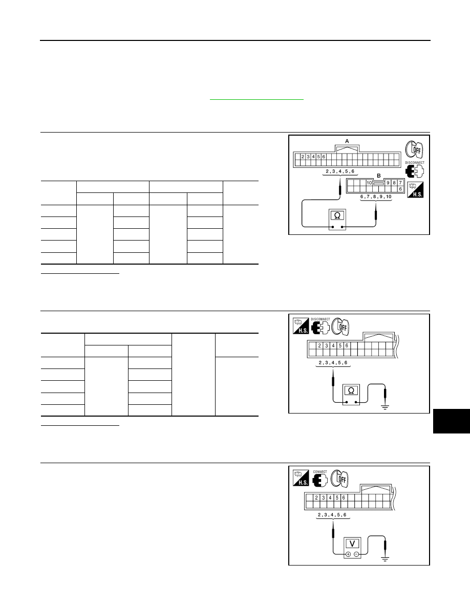
1.
CHECK INPUT 1 - 5 SYSTEM CIRCUIT FOR OPEN
1. Turn ignition switch OFF.
2. Disconnect BCM and combination switch.
3. Check continuity between BCM harness connector and combi-
nation switch harness connector.
Does continuity exist?
YES
>> GO TO 2
NO
>> Repair or replace harness.
2.
CHECK INPUT 1 - 5 SYSTEM CIRCUIT FOR SHORT
Check for continuity between BCM harness connector and ground.
Does continuity exist?
YES
>> Repair or replace harness.
NO
>> GO TO 3
3.
CHECK BCM OUTPUT VOLTAGE
1. Connect BCM.
2. Turn ignition switch ON.
3. Check voltage between BCM harness connector and ground.
System
BCM
Combination switch
Continuity
Connector
Terminal
Connector
Terminal
INPUT 1
M18
(A)
6
M28
(B)
6
Yes
INPUT 2
5
7
INPUT 3
4
10
INPUT 4
3
9
INPUT 5
2
8
ALMIA0275ZZ
System
BCM
Ground
Continuity
Connector
Terminal
INPUT 1
M18
6
No
INPUT 2
5
INPUT 3
4
INPUT 4
3
INPUT 5
2
ALMIA0276ZZ
ALMIA0277ZZ