Content .. 1018 1019 1020 1021 ..
Infiniti QX56 (JA60). Manual - part 1020
WT-8
< FUNCTION DIAGNOSIS >
TPMS
FUNCTION DIAGNOSIS
TPMS
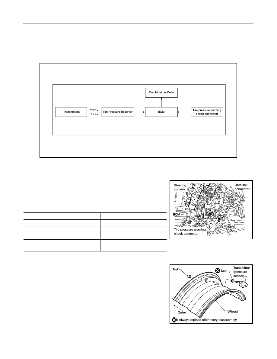
System Diagram
INFOID:0000000005148206
System Description
INFOID:0000000005148207
BODY CONTROL MODULE (BCM)
The BCM is shown with the lower instrument panel LH removed. The
BCM reads the air pressure signal received by the remote keyless
entry receiver, and controls the low tire pressure warning lamp as
shown below. It also has a self-diagnosis function to detect a system
malfunction.
TRANSMITTER
A sensor-transmitter integrated with a valve is installed in each
wheel, and transmits a detected air pressure signal in the form of a
radio wave. The radio signal is received by the remote keyless entry
receiver.
REMOTE KEYLESS ENTRY RECEIVER
ALEIA0004GB
Condition
Low tire pressure warning lamp
System normal
On for 1 second after ignition ON
Tire less than 193 kPa (2.0 kg/cm
2
, 28 psi)
[Flat tire]
ON
TPMS malfunction
After key ON, flashes once per sec-
ond for 1 minute, then stays ON
LEIA0068E
WEIA0137E