Infiniti QX56 (JA60). Manual - part 66
AV-72
< COMPONENT DIAGNOSIS >
[AUDIO SYSTEM]
POWER SUPPLY AND GROUND CIRCUIT
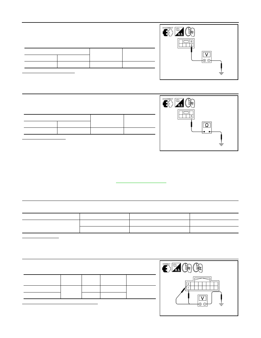
1. Turn ignition switch OFF.
2. Disconnect subwoofer connector.
3. Check voltage between subwoofer harness connector B72 ter-
minal 6 and ground.
Is battery voltage present?
YES
>> GO TO 3.
NO
>> Check harness between subwoofer and fuse.
3.
CHECK GROUND CIRCUIT
1. Turn ignition switch OFF.
2. Check continuity between subwoofer harness connector B72
terminal 5 and ground.
Does continuity exist?
YES
>> Inspection End.
NO
>> Repair harness or connector.
REAR VIEW CAMERA CONTROL UNIT
REAR VIEW CAMERA CONTROL UNIT : Diagnosis Procedure
INFOID:0000000005146306
Regarding Wiring Diagram information, refer to
.
1.
CHECK FUSE
Check that the following fuses of the rear view camera control unit are not blown.
Are the fuses OK?
YES
>> GO TO 2.
NO
>> Be sure to eliminate cause of malfunction before installing new fuse.
2.
CHECK POWER SUPPLY CIRCUIT
Check voltage between rear view camera control unit harness con-
nector B73 and ground.
Are the voltage readings as specified?
YES
>> GO TO 3.
NO
>> Check harness between rear view camera control unit
and fuse.
(+)
(-)
Voltage (approx.)
Connector
Terminal
B72
6
Ground
Battery voltage
ALNIA0367GB
(+)
(-)
Continuity
Connector
Terminal
B72
5
Ground
Yes
ALNIA0368GB
Unit
Terminals
Signal name
Fuse No.
Rear view camera control unit
1
Battery power
31
2
Ignition switch ACC or ON
4
Signal name
Connector
Terminal
Ignition switch
position
Value (Approx.)
Battery power supply
B73
1
OFF
Battery voltage
ACC power supply
2
ACC
ALLIA0244ZZ