Infiniti QX56 (JA60). Manual - part 21


  Index      Infiniti     Infiniti QX56 (JA60) - service repair manual 2010 year


Search            


Content   ..  19  20  21  22   ..


Infiniti QX56 (JA60). Manual - part 21


DOOR MIRROR REMOTE CONTROL SWITCH

ADP-75

< COMPONENT DIAGNOSIS >

C

D

E

F

G

H

I

K

L

M

A

B

ADP

N

O

P

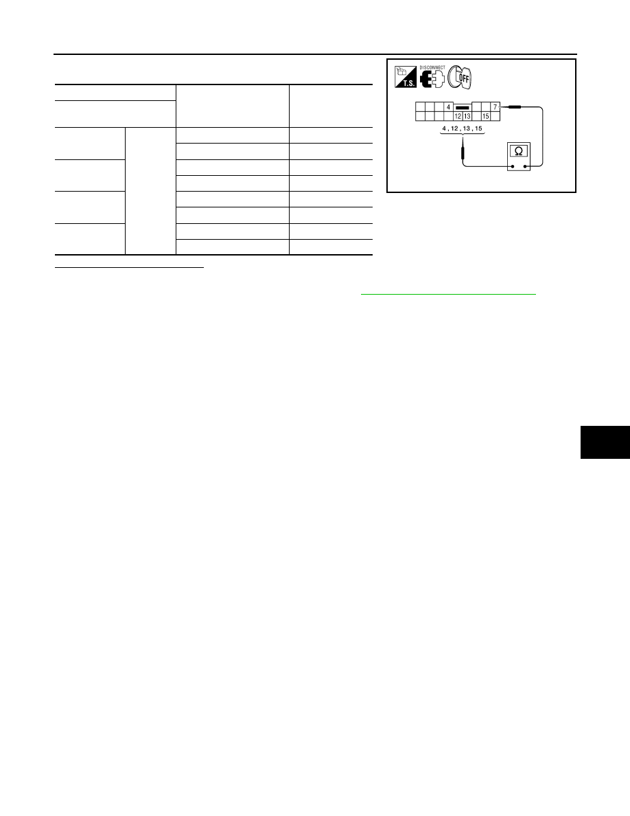
Check door mirror remote control switch.

Is the inspection result normal?

YES

>> Inspection End.

NO

>> Replace door mirror remote control switch. Refer to 

ADP-177, "Removal and Installation"

.

Terminal

Mirror switch condition

Continuity

Door mirror remote 

control switch

4

7

RIGHT

Yes

Other than above

No

13

LEFT

Yes

Other than above

No

15

UP

Yes

Other than above

No

12

DOWN

Yes

Other than above

No

AWJIA0239ZZ

ADP-76

< COMPONENT DIAGNOSIS >

POWER SEAT SWITCH GROUND CIRCUIT

POWER SEAT SWITCH GROUND CIRCUIT

Diagnosis Procedure

INFOID:0000000005147518

Regarding Wiring Diagram information, refer to 

ADP-119, "Wiring Diagram"

.

1.

 CHECK POWER SEAT SWITCH LH GROUND CIRCUIT

1. Turn ignition switch OFF.

2. Disconnect power seat switch LH.

3. Check continuity between power seat switch LH connector and

ground.

Is the inspection result normal?

YES

>> Check intermittent incident. Refer to 

GI-38, "Intermittent

Incident"

.

NO

>> Repair or replace harness.

Power seat switch LH 

connector

Terminal

Ground

Continuity

B208

7

Yes

ALJIA0316ZZ

DETENTION SWITCH

ADP-77

< COMPONENT DIAGNOSIS >

C

D

E

F

G

H

I

K

L

M

A

B

ADP

N

O

P

DETENTION SWITCH

Description

INFOID:0000000005147519

Park position switch is installed on A/T shift selector. It is turned OFF when the A/T selector lever is in P posi-

tion. The driver seat control unit judges that the A/T selector lever is in P position if continuity does not exist in

this circuit.

Component Function Check

INFOID:0000000005147520

1.

 CHECK FUNCTION

1. Select  “DETENT SW” signal in “Data monitor” mode with CONSULT-III. 

2. Check park position switch signal under the following conditions.

Is the indication normal?

YES

>> Inspection End.

NO

>> Perform diagnosis procedure. Refer to 

ADP-77, "Diagnosis Procedure"

.

Diagnosis Procedure

INFOID:0000000005147521

Regarding Wiring Diagram information, refer to 

ADP-119, "Wiring Diagram"

.

1.

 CHECK DTC WITH “BCM”

Check “Self Diagnostic Result” for BCM with CONSULT-lll.
Is any other DTC detected?

YES

>> Check the DTC. 

NO

>> GO TO 2

2.

 CHECK PARK POSITION SWITCH INPUT SIGNAL

1. Turn ignition switch ON.

2. Mechanical key must be removed from the key switch.

3. Check voltage between driver seat control unit harness connec-

tor and ground. 

Is the inspection result normal?

YES

>> GO TO 4

NO

>> GO TO 3

3.

 CHECK PARK POSITION SWITCH CIRCUIT

Monitor item

Condition

Status

DETENT SW

A/T selector lever

P position

OFF

Other than 
above

ON

Driver seat 
control unit 

connector

Terminal

Condition

Voltage (V)

(Approx.)

(+)

(-)

B202

21

Ground

A/T selec-
tor lever

P position

Battery volt-

age

Other than 
above

0V

ALJIA0193ZZ

ADP-78

< COMPONENT DIAGNOSIS >

DETENTION SWITCH

1. Turn ignition switch OFF.

2. Disconnect driver seat control unit and A/T shift selector.

3. Check continuity between driver seat control unit harness con-

nector (A) and A/T shift selector harness connector (B).

4. Check continuity between driver seat control unit harness con-

nector (A) and ground.

Is the inspection result normal?

YES

>> GO TO 4

NO

>> Repair or replace harness.

4.

 CHECK INTERMITTENT INCIDENT

Refer to 

GI-38, "Intermittent Incident"

.

Is the inspection result normal?

YES

>> Replace driver seat control unit. Refer to 

ADP-174, "Removal and Installation"

.

NO

>> Repair or replace the malfunctioning part.

A

B

Continuity

Connector

Terminal

Connector

Terminal

B202

21

M203

6

Yes

A

Ground

Continuity 

Connector

Terminal

B202

21

No

ALJIA0194ZZ


Content   ..  19  20  21  22   ..