Infiniti QX56 (JA60). Manual - part 7


  Index      Infiniti     Infiniti QX56 (JA60) - service repair manual 2010 year


Search            


Content   ..  5  6  7  8   ..


Infiniti QX56 (JA60). Manual - part 7


AUTOMATIC DRIVE POSITIONER SYSTEM

ADP-19

< FUNCTION DIAGNOSIS >

C

D

E

F

G

H

I

K

L

M

A

B

ADP

N

O

P

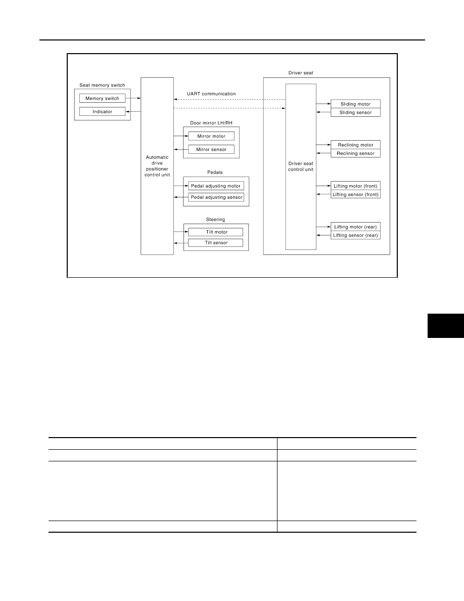
MEMORY FUNCTION : System Diagram

INFOID:0000000005147433

MEMORY FUNCTION : System Description

INFOID:0000000005147434

OUTLINE

The driver seat control unit can store the optimum driving positions (seat, pedal assembly, steering wheel and

door mirror position) for 2 people. If the front seat position is changed, one-touch (pressing desired memory

switch for more than 0.5 second) operation allows changing to the other driving position.

NOTE:

Further information for the memory storage procedure. Refer to Owner’s Manual. 

OPERATION PROCEDURE

1. Turn ignition switch ON.

2. Press desired memory switch for more than 0.5 second.

3. Front seat LH, pedal assembly, steering wheel and door mirror will move to the memorized position.

OPERATION CONDITION

Satisfy all of the following items. The memory function is not performed if these items are not satisfied.

DETAIL FLOW

ALJIA0237GB

Item

Request status

Ignition position

ON

Switch inputs
• Power seat switch
• Pedal adjusting switch
• ADP steering switch
• Door mirror control switch
• Set switch
• Seat memory switch

OFF

(Not operated)

A/T selector lever

P position

ADP-20

< FUNCTION DIAGNOSIS >

AUTOMATIC DRIVE POSITIONER SYSTEM

MEMORY FUNCTION : Component Parts Location

INFOID:0000000005370290

Order

Input

Output

Control unit condition

1

Memory switch

The memory switch signal is inputted to the automatic drive positioner 
control unit when memory switch 1 or 2 is operated.
Memory switch signal is input to driver seat control unit via UART 
communication.

2

Motors
(seat, pedal adjusting, 
tilt, door mirror)

Driver seat control unit operates each motor of seat when it recogniz-
es the memory switch pressed for 0.5 second or more and requests 
each motor operation to automatic drive positioner control unit via 
UART communication. The automatic drive positioner control unit op-
erates each motor.

Memory switch Indica-
tor

Driver seat control unit requests the flashing of memory indicator to 
automatic drive positioner control unit via UART communication while 
either of the motors is operating. The automatic drive positioner con-
trol unit illuminates the memory indicator.

3

Sensors
(seat, pedal adjust-
ing, tilt, door mirror)

Driver seat control unit judges the operating seat position with each 
seat sensor input. The positions of the adjustable pedals and outside 
mirror are monitored with each sensor signal that is input from auto 
drive positioner control unit via UART communication. Driver seat 
control unit stops the operation of each motor when each part reach-
es the recorded address.

4

Memory switch Indica-
tor

Driver seat control unit requests the illumination of memory indicator 
to auto drive positioner control unit via UART communication after all 
motors stop. The auto driving positioner control unit illuminates the 
memory indicator for 5 seconds.

ALJIA0347ZZ

AUTOMATIC DRIVE POSITIONER SYSTEM

ADP-21

< FUNCTION DIAGNOSIS >

C

D

E

F

G

H

I

K

L

M

A

B

ADP

N

O

P

MEMORY FUNCTION : Component Description

INFOID:0000000005147436

CONTROL UNITS

INPUT PARTS

Switches

Sensors

OUTPUT PARTS

1.

A. Automatic drive positioner control 
unit M33, M34
B. Pedal adjusting motor assembly 
E109, E110

2.

A. Steering column
B. Key switch and ignition knob 
switch M12
C. BCM M18, M19, M20 (view with 
instrument panel removed)

3.

A. Door mirror remote control switch 
D10
B. Seat memory switch D5

4.

Pedal adjusting switch M96

5.

A. Door mirrror LH D4, RH D107
B. Front door switch LH B

6.

A. A/T selector lever
B. A/T shift selector (park position 
switch) M203

7.

A. Sliding motor LH B204 (driver seat 
view), reclining motor LH B205, lift-
ing motor (front) B206, lifting motor 
(rear) B207
B. Driver seat control unit B202, 
B203
C. Power seat switch LH B208

8.

A. ADP steering switch M16
B. Tilt sensor M85 and tilt motor M86

Item

Function

Driver seat control unit

• The address of each part is recorded.
• Operates each motor of seat to the registered position.
• Requests the operations of pedal assembly and door mirror to automatic drive po-

sitioner control unit.

Automatic drive positioner control unit

Operates the pedal adjusting motor, tilt motor and door mirror with the instructions 
from the driver seat control.

Item

Function

Memory switch 1/2

The registration and memory function can be performed with its operation.

Item

Function

Door mirror sensor (LH/RH)

Detect the up/down and left/right position of outside mirror face.

Pedal adjusting sensor

Detect the forward/backward position of pedal assembly.

Tilt sensor

Detect the upward/downward position of steering wheel.

Lifting sensor (front)

Detect the up/down position of seat lifting (front).

Lifting sensor (rear)

Detect the up/down position of seat lifting (rear).

Reclining sensor

Detect the tilt of seatback.

Sliding sensor

Detect the front/rear position of seat.

Item

Function

Door mirror motor (LH/RH)

Move the outside mirror face upward/downward and left/right.

Pedal adjusting motor

Move the pedal assembly forward/backward.

Tilt motor

Move the steering wheel upward/downward.

Lifting motor (front)

Move the seat lifter (front) upward/downward.

Lifting motor (rear)

Move the seat lifter (rear) upward/downward.

Reclining motor

Tilt and raise up the seatback.

ADP-22

< FUNCTION DIAGNOSIS >

AUTOMATIC DRIVE POSITIONER SYSTEM

EXIT ASSIST FUNCTION
EXIT ASSIST FUNCTION : System Diagram

INFOID:0000000005147437

EXIT ASSIST FUNCTION : System Description

INFOID:0000000005147438

OUTLINE

When exiting, if the conditions are satisfied, the seat is moved backward and steering wheel is moved upward-

from normal sitting position.

The seat slide amount at entry/exit operation can be changed.

NOTE:

• This function is set to OFF before delivery (initial setting).

• Further information for the system setting procedure. Refer to Owner’s Manual.

OPERATION PROCEDURE

1. Open the driver door with ignition switch in OFF position.

2. Front seat LH and steering wheel will move to the exiting position.

OPERATION CONDITION

Satisfy all of the following items. The exit assist function is not performed if these items are not satisfied.

Sliding motor

Slide the seat forward/backward.

Memory indicator

Illuminates or blinks according to the registration/operation status.

Item

Function

ALJIA0238GB

Item

Request status

Ignition switch

OFF

System setting [Entry/exit assist function]

ON

Initialization

Done


Content   ..  5  6  7  8   ..