Infiniti QX56 (Z62). Manual - part 955


  Index      Infiniti     Infiniti QX56 (Z62) - service repair manual 2011 year


Search            


Content   ..  953  954  955  956   ..


Infiniti QX56 (Z62). Manual - part 955


MWI-74

< DTC/CIRCUIT DIAGNOSIS >

A/C AUTO AMP. CONNECTION RECOGNITION SIGNAL CIRCUIT

A/C AUTO AMP. CONNECTION RECOGNITION SIGNAL CIRCUIT

Diagnosis Procedure

INFOID:0000000006221756

1.

CHECK A/C AUTO AMP. CONNECTION RECOGNITION SIGNAL

1.

Turn ignition switch ON.

2.

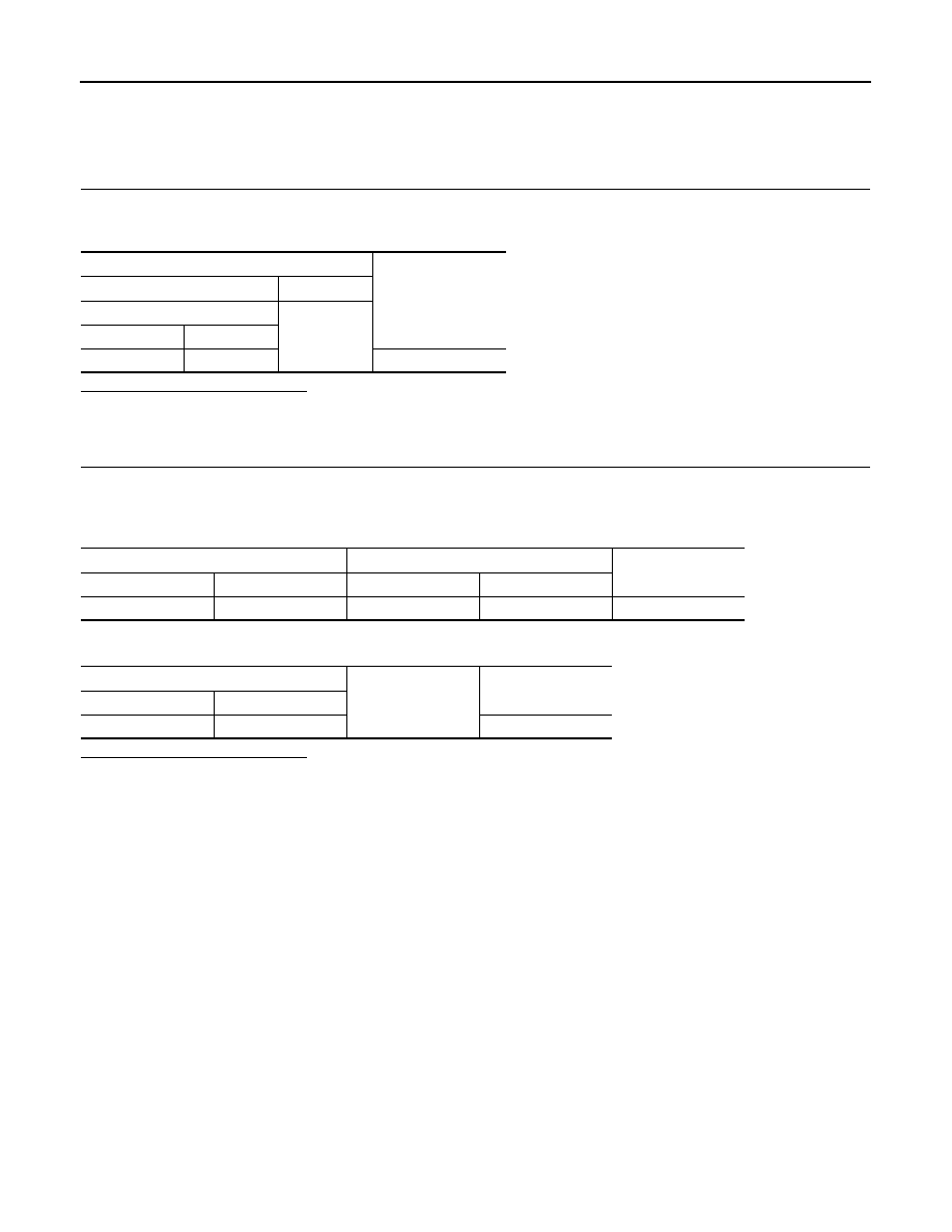
Check voltage between combination meter harness connector and ground.

Is the inspection result normal?

YES

>> INSPECTION END

NO

>> GO TO 2.

2.

CHECK A/C AUTO AMP. CONNECTION RECOGNITION SIGNAL CIRCUIT

1.

Turn ignition switch OFF.

2.

Disconnect combination meter connector and A/C auto amp. connector.

3.

Check continuity between combination meter harness connector and A/C auto amp. harness connector.

4.

Check continuity between combination meter harness connector and ground.

Is the inspection result normal?

YES

>> INSPECTION END

NO

>> Repair harness or connector.

Terminals

Voltage

(Approx.)

(+)

(

)

Combination meter

Ground

Connector

Terminal

M34

19

5 V

Combination meter

A/C auto amp.

Continuity

Connector

Terminal

Connector

Terminal

M34

19

M50

6

Existed

Combination meter

Ground

Continuity

Connector

Terminal

M34

19

Not existed

MWI

THE FUEL GAUGE INDICATOR DOES NOT OPERATE

MWI-75

< SYMPTOM DIAGNOSIS >

C

D

E

F

G

H

I

J

K

L

M

B

A

O

P

SYMPTOM DIAGNOSIS

THE FUEL GAUGE INDICATOR DOES NOT OPERATE

Description

INFOID:0000000006221757

Fuel gauge will not indicate from a certain position.

Diagnosis Procedure

INFOID:0000000006221758

1.

CHECK COMBINATION METER OUTPUT SIGNAL

1.

Connect CONSULT-III.

2.

Select the “Data Monitor” for the “METER/M&A” and compare the “FUEL METER” monitor value with the
fuel gauge reading on the combination meter. Refer to 

MWI-69, "Component Function Check"

.

Does monitor value match fuel gauge reading?

YES

>> GO TO 2.

NO

>> Replace combination meter. Refer to 

MWI-85, "Removal and Installation"

.

2.

CHECK FUEL LEVEL SENSOR SIGNAL CIRCUIT

Check the fuel level sensor signal circuit. Refer to 

MWI-69, "Diagnosis Procedure"

.

Is the inspection result normal?

YES

>> GO TO 3.

NO

>> Repair harness or connector.

3.

CHECK FUEL LEVEL SENSOR UNIT

Perform a unit check for the fuel level sensor unit. Refer to 

MWI-70, "Component Inspection"

.

Is the inspection result normal?

YES

>> GO TO 4.

NO

>> Replace fuel level sensor unit. Refer to 

FL-5, "Removal and Installation"

.

4.

CHECK FLOAT INTERFERENCE

Check that the float arm interferes with or binds to other components in the fuel tank.
Is the inspection result normal?

YES

>> Replace combination meter. Refer to 

MWI-85, "Removal and Installation"

.

NO

>> Repair or replace malfunctioning parts.

MWI-76

< SYMPTOM DIAGNOSIS >

THE TRIP RESET AND ILLUMINATION CONTROL SWITCH IS INOPERATIVE

THE TRIP RESET AND ILLUMINATION CONTROL SWITCH IS INOPERA-
TIVE

Description

INFOID:0000000006221759

If any of the following malfunctions is found for the trip reset and illumination control switch operation.
• All switches are inoperative
• The specified switch cannot be operated

Diagnosis Procedure

INFOID:0000000006221760

1.

CHECK TRIP RESET AND ILLUMINATION CONTROL SWITCH SIGNAL CIRCUIT

Check the trip reset and illumination control switch signal circuit. Refer to 

MWI-65, "Diagnosis Procedure"

Is the inspection result normal?

YES

>> GO TO 2.

NO

>> Repair harness or connector.

2.

CHECK TRIP RESET AND ILLUMINATION CONTROL SWITCH

Perform a unit check for the trip reset and illumination control switch. Refer to 

MWI-66, "Component Inspec-

tion"

Is the inspection result normal?

YES

>> Replace combination meter. Refer to 

MWI-85, "Removal and Installation"

.

NG

>> Replace trip reset and illumination control switch. Refer to 

MWI-86, "Removal and Installation"

.

MWI

THE TRIP COMPUTER SWITCH IS INOPERATIVE

MWI-77

< SYMPTOM DIAGNOSIS >

C

D

E

F

G

H

I

J

K

L

M

B

A

O

P

THE TRIP COMPUTER SWITCH IS INOPERATIVE

Description

INFOID:0000000006221761

If any of the following malfunctions is found for the trip computer switch operation.
• All switches are inoperative
• The specified switch cannot be operated

Diagnosis Procedure

INFOID:0000000006221762

1.

CHECK TRIP COMPUTER SWITCH SIGNAL CIRCUIT

Check the trip computer switch signal circuit. Refer to 

MWI-67, "Diagnosis Procedure"

Is the inspection result normal?

YES

>> GO TO 2.

NO

>> Repair harness or connector.

2.

CHECK TRIP COMPUTER SWITCH

Perform a unit check for the trip computer switch. Refer to 

MWI-68, "Component Inspection"

Is the inspection result normal?

YES

>> Replace combination meter. Refer to 

MWI-85, "Removal and Installation"

.

NG

>> Replace trip computer switch. Refer to 

MWI-87, "Removal and Installation"

.


Content   ..  953  954  955  956   ..