Infiniti QX56 (Z62). Manual - part 927


  Index      Infiniti     Infiniti QX56 (Z62) - service repair manual 2011 year


Search            


Content   ..  925  926  927  928   ..


Infiniti QX56 (Z62). Manual - part 927


SERVICE DATA AND SPECIFICATIONS (SDS)

MA-35

< SERVICE DATA AND SPECIFICATIONS (SDS) 

C

D

E

F

G

H

I

J

K

L

M

B

MA

N

O

A

SERVICE DATA AND SPECIFICATIONS (SDS)

SERVICE DATA AND SPECIFICATIONS (SDS)

DRIVE BELTS

DRIVE BELTS : Drive Belts

INFOID:0000000006394853

DRIVE BELT

ENGINE COOLANT

ENGINE COOLANT : Periodical Maintenance Specification

INFOID:0000000006394856

ENGINE COOLANT CAPACITY (APPROXIMATELY)

Unit: 

 (US qt, Imp qt)

ENGINE OIL

ENGINE OIL : Periodical Maintenance Specification

INFOID:0000000006394855

ENGINE OIL CAPACITY (APPROXIMATE)

Unit: 

 (US qt, Imp qt)

SPARK PLUG

SPARK PLUG : Spark Plug

INFOID:0000000006394854

SPARK PLUG

Unit: mm (in)

ROAD WHEEL

ROAD WHEEL : Road Wheel

INFOID:0000000006349771

ALUMINUM WHEEL

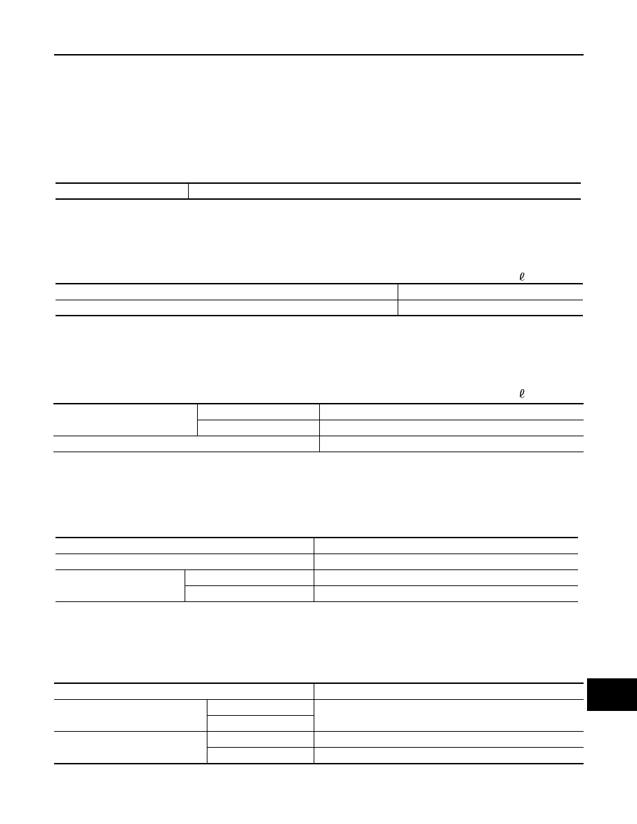
Tension of drive belts

Belt tension is not necessary, as it is automatically adjusted by drive belt auto-tensioner.

Engine coolant capacity [With reservoir tank (“MAX” level)]

14.9 (15-6/8, 13-1/8)

Reservoir tank engine coolant capacity (At “MAX” level)

1.0 (1, 7/8)

Drain and refill

With oil filter change

6.5 (6-7/8, 5-3/4)

Without oil filter change

6.2 (6-4/8, 5-1/2)

Dry engine (engine overhaul)

7.6 (8, 6-3/4)         

Make

NGK

Standard type

DILKAR7B11

Gap 

Standard

1.1 (0.043)

Limit

1.25 (0.049)

Item

Limit

Radial runout

Lateral deflection

Less than 0.3 mm (0.012 in)

Vertical deflection

Allowable unbalance

Dynamic (At flange)

Less than 7 g (0.25 oz) (one side)

Static (At flange)

Less than 14 g (0.49 oz)

MIR-1

DRIVER CONTROLS

C

D

E

F

G

H

I

J

K

M

SECTION 

MIR

A

B

MIR

N

O

P

CONTENTS

MIRRORS

PRECAUTION ...............................................

3

PRECAUTIONS ...................................................

3

Precaution for Supplemental Restraint System 
(SRS) "AIR BAG" and "SEAT BELT PRE-TEN-
SIONER" .................................................................
..

3

Precaution Necessary for Steering Wheel Rota-
tion after Battery Disconnect  ...................................
..

3

PREPARATION ............................................

5

PREPARATION ...................................................

5

Commercial Service Tools .......................................

5

SYSTEM DESCRIPTION  ..............................

6

COMPONENT PARTS  ........................................

6

DOOR MIRROR  ...........................................................

6

DOOR MIRROR : Component Parts Location  ..........

6

DOOR MIRROR : Component Description  ...............

6

INSIDE MIRROR ..........................................................

7

INSIDE MIRROR : Component Description  ..............

7

SYSTEM ..............................................................

8

DOOR MIRROR SYSTEM  ...........................................

8

DOOR MIRROR SYSTEM : System Diagram  ..........

8

DOOR MIRROR SYSTEM : System Description ......

8

AUTO ANTI-DAZZLING INSIDE MIRROR SYS-
TEM ............................................................................
..

9

AUTO ANTI-DAZZLING INSIDE MIRROR SYS-
TEM : System Description .......................................
..

9

ECU DIAGNOSIS INFORMATION ..............

10

DRIVER SEAT CONTROL UNIT, AUTOMAT-
IC DRIVE POSITIONER CONTROL UNIT  .........

10

List of ECU Reference  ............................................

10

WIRING DIAGRAM  ......................................

11

DOOR MIRROR SYSTEM .................................

11

Wiring Diagram ........................................................

11

AUTO ANTI-DAZZLING INSIDE MIRROR 
SYSTEM ............................................................

19

Wiring Diagram - INSIDE MIRROR SYSTEM -  .......

19

BASIC INSPECTION  ...................................

21

DIAGNOSIS AND REPAIR WORKFLOW  ........

21

Work Flow ................................................................

21

DTC/CIRCUIT DIAGNOSIS  .........................

22

DOOR MIRROR REMOTE CONTROL 
SWITCH .............................................................

22

OPEN/CLOSE SWITCH .............................................

22

OPEN/CLOSE SWITCH : Component Inspection ....

22

SYMPTOM DIAGNOSIS  ..............................

23

REVERSE INTERLOCK DOOR MIRROR 
DOES NOT OPERATE ......................................

23

Diagnosis Procedure  ...............................................

23

SQUEAK AND RATTLE TROUBLE DIAG-
NOSES ..............................................................

24

Work Flow ................................................................

24

Inspection Procedure ...............................................

26

Diagnostic Worksheet ..............................................

28

REMOVAL AND INSTALLATION  ...............

30

INSIDE MIRROR  ...............................................

30

Exploded View .........................................................

30

Removal and Installation  .........................................

30

OUTSIDE MIRROR  ...........................................

32

Exploded View .........................................................

32

DOOR MIRROR ASSEMBLY  ....................................

32

PRECAUTIONS

MIR-3

< PRECAUTION >

C

D

E

F

G

H

I

J

K

M

A

B

MIR

N

O

P

PRECAUTION

PRECAUTIONS

Precaution for Supplemental Restraint System (SRS) "AIR BAG" and "SEAT BELT 
PRE-TENSIONER"

INFOID:0000000006257245

The Supplemental Restraint System such as “AIR BAG” and “SEAT BELT PRE-TENSIONER”, used along
with a front seat belt, helps to reduce the risk or severity of injury to the driver and front passenger for certain
types of collision. This system includes seat belt switch inputs and dual stage front air bag modules. The SRS
system uses the seat belt switches to determine the front air bag deployment, and may only deploy one front
air bag, depending on the severity of a collision and whether the front occupants are belted or unbelted.
Information necessary to service the system safely is included in the “SRS AIR BAG” and “SEAT BELT” of this
Service Manual.

WARNING:

• To avoid rendering the SRS inoperative, which could increase the risk of personal injury or death in

the event of a collision that would result in air bag inflation, all maintenance must be performed by
an authorized NISSAN/INFINITI dealer.

• Improper maintenance, including incorrect removal and installation of the SRS, can lead to personal

injury caused by unintentional activation of the system. For removal of Spiral Cable and Air Bag
Module, see the “SRS AIR BAG”.

• Do not use electrical test equipment on any circuit related to the SRS unless instructed to in this

Service Manual. SRS wiring harnesses can be identified by yellow and/or orange harnesses or har-
ness connectors.

PRECAUTIONS WHEN USING POWER TOOLS (AIR OR ELECTRIC) AND HAMMERS

WARNING:

• When working near the Air Bag Diagnosis Sensor Unit or other Air Bag System sensors with the

ignition ON or engine running, DO NOT use air or electric power tools or strike near the sensor(s)
with a hammer. Heavy vibration could activate the sensor(s) and deploy the air bag(s), possibly
causing serious injury.

• When using air or electric power tools or hammers, always switch the ignition OFF, disconnect the

battery, and wait at least 3 minutes before performing any service.

Precaution Necessary for Steering Wheel Rotation after Battery Disconnect

INFOID:0000000006257246

NOTE:
• Before removing and installing any control units, first turn the push-button ignition switch to the LOCK posi-

tion, then disconnect both battery cables.

• After finishing work, confirm that all control unit connectors are connected properly, then re-connect both

battery cables.

• Always use CONSULT-III to perform self-diagnosis as a part of each function inspection after finishing work.

If a DTC is detected, perform trouble diagnosis according to self-diagnosis results.

For vehicle with steering lock unit, if the battery is disconnected or discharged, the steering wheel will lock and
cannot be turned.
If turning the steering wheel is required with the battery disconnected or discharged, follow the operation pro-
cedure below before starting the repair operation.

OPERATION PROCEDURE

1.

Connect both battery cables.
NOTE:
Supply power using jumper cables if battery is discharged.

2.

Turn the push-button ignition switch to ACC position.
(At this time, the steering lock will be released.)

3.

Disconnect both battery cables. The steering lock will remain released with both battery cables discon-
nected and the steering wheel can be turned.

4.

Perform the necessary repair operation.


Content   ..  925  926  927  928   ..