Infiniti QX56 (Z62). Manual - part 902


  Index      Infiniti     Infiniti QX56 (Z62) - service repair manual 2011 year


Search            


Content   ..  900  901  902  903   ..


Infiniti QX56 (Z62). Manual - part 902


LAN

DLC BRANCH LINE CIRCUIT

LAN-185

< DTC/CIRCUIT DIAGNOSIS >

[CAN SYSTEM (TYPE 3)]

C

D

E

F

G

H

I

J

K

L

B

A

O

P

N

DLC BRANCH LINE CIRCUIT

Diagnosis Procedure

INFOID:0000000006256343

1.

CHECK CONNECTOR

1.

Turn the ignition switch OFF.

2.

Disconnect the battery cable from the negative terminal.

3.

Check the terminals and connectors of the data link connector for damage, bend and loose connection
(connector side and harness side).

Is the inspection result normal?

YES

>> GO TO 2.

NO

>> Repair the terminal and connector.

2.

CHECK HARNESS FOR OPEN CIRCUIT

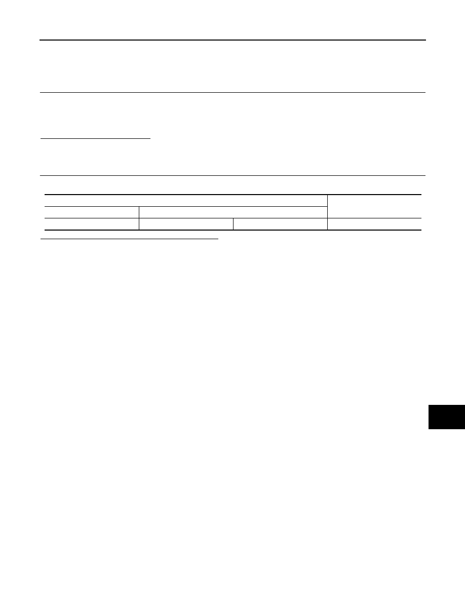
Check the resistance between the data link connector terminals.

Is the measurement value within the specification?

YES (Present error)>>Check CAN system type decision again.
YES (Past error)>>Error was detected in the data link connector branch line circuit.
NO

>> Repair the data link connector branch line.

Data link connector

Resistance (

)

Connector No.

Terminal No.

M4

6

14

Approx. 54 – 66

LAN-186

< DTC/CIRCUIT DIAGNOSIS >

[CAN SYSTEM (TYPE 3)]

HVAC BRANCH LINE CIRCUIT

HVAC BRANCH LINE CIRCUIT

Diagnosis Procedure

INFOID:0000000006256344

1.

CHECK CONNECTOR

1.

Turn the ignition switch OFF.

2.

Disconnect the battery cable from the negative terminal.

3.

Check the terminals and connectors of the A/C auto amp. for damage, bend and loose connection (unit
side and connector side).

Is the inspection result normal?

YES

>> GO TO 2.

NO

>> Repair the terminal and connector.

2.

CHECK HARNESS FOR OPEN CIRCUIT

1.

Disconnect the connector of A/C auto amp.

2.

Check the resistance between the A/C auto amp. harness connector terminals.

Is the measurement value within the specification?

YES

>> GO TO 3.

NO

>> Repair the A/C auto amp. branch line.

3.

CHECK POWER SUPPLY AND GROUND CIRCUIT

Check the power supply and the ground circuit of the A/C auto amp. Refer to 

HAC-110, "A/C AUTO AMP. :

Diagnosis Procedure"

.

Is the inspection result normal?

YES (Present error)>>Replace the A/C auto amp. Refer to 

HAC-146, "Removal and Installation"

.

YES (Past error)>>Error was detected in the A/C auto amp. branch line.
NO

>> Repair the power supply and the ground circuit.

A/C auto amp. harness connector

Resistance (

)

Connector No.

Terminal No.

M50

1

21

Approx. 54 – 66

LAN

M&A BRANCH LINE CIRCUIT

LAN-187

< DTC/CIRCUIT DIAGNOSIS >

[CAN SYSTEM (TYPE 3)]

C

D

E

F

G

H

I

J

K

L

B

A

O

P

N

M&A BRANCH LINE CIRCUIT

Diagnosis Procedure

INFOID:0000000006256345

1.

CHECK CONNECTOR

1.

Turn the ignition switch OFF.

2.

Disconnect the battery cable from the negative terminal.

3.

Check the terminals and connectors of the combination meter for damage, bend and loose connection
(unit side and connector side).

Is the inspection result normal?

YES

>> GO TO 2.

NO

>> Repair the terminal and connector.

2.

CHECK HARNESS FOR OPEN CIRCUIT

1.

Disconnect the connector of combination meter.

2.

Check the resistance between the combination meter harness connector terminals.

Is the measurement value within the specification?

YES

>> GO TO 3.

NO

>> Repair the combination meter branch line.

3.

CHECK POWER SUPPLY AND GROUND CIRCUIT

Check the power supply and the ground circuit of the combination meter. Refer to 

MWI-64, "COMBINATION

METER : Diagnosis Procedure"

.

Is the inspection result normal?

YES (Present error)>>Replace the combination meter. Refer to 

MWI-85, "Removal and Installation"

.

YES (Past error)>>Error was detected in the combination meter branch line.
NO

>> Repair the power supply and the ground circuit.

Combination meter harness connector

Resistance (

)

Connector No.

Terminal No.

M34

21

22

Approx. 54 – 66

LAN-188

< DTC/CIRCUIT DIAGNOSIS >

[CAN SYSTEM (TYPE 3)]

STRG BRANCH LINE CIRCUIT

STRG BRANCH LINE CIRCUIT

Diagnosis Procedure

INFOID:0000000006256346

1.

CHECK CONNECTOR

1.

Turn the ignition switch OFF.

2.

Disconnect the battery cable from the negative terminal.

3.

Check the terminals and connectors of the steering angle sensor for damage, bend and loose connection
(unit side and connector side).

Is the inspection result normal?

YES

>> GO TO 2.

NO

>> Repair the terminal and connector.

2.

CHECK HARNESS FOR OPEN CIRCUIT

1.

Disconnect the connector of steering angle sensor.

2.

Check the resistance between the steering angle sensor harness connector terminals.

Is the measurement value within the specification?

YES

>> GO TO 3.

NO

>> Repair the steering angle sensor branch line.

3.

CHECK POWER SUPPLY AND GROUND CIRCUIT

Check the power supply and the ground circuit of the steering angle sensor. Refer to 

BRC-53, "Wiring Dia-

gram"

.

Is the inspection result normal?

YES (Present error)>>Replace the steering angle sensor. Refer to 

BRC-139, "Removal and Installation"

.

YES (Past error)>>Error was detected in the steering angle sensor branch line.
NO

>> Repair the power supply and the ground circuit.

Steering angle sensor harness connector

Resistance (

)

Connector No.

Terminal No.

M30

5

2

Approx. 54 – 66


Content   ..  900  901  902  903   ..