Infiniti QX56 (Z62). Manual - part 899
LAN
ITS COMMUNICATION CIRCUIT
LAN-173
< DTC/CIRCUIT DIAGNOSIS >
[CAN SYSTEM (TYPE 2)]
C
D
E
F
G
H
I
J
K
L
B
A
O
P
N
ITS COMMUNICATION CIRCUIT
Diagnosis Procedure
INFOID:0000000006256315
1.
CHECK CAN DIAGNOSIS
Check the CAN diagnosis results from CONSULT-III to see that the CAN communication circuit 1 and CAN
communication circuit 2 have no malfunction.
NOTE:
For identification of CAN communication circuit 1, CAN communication circuit 2, and ITS communication cir-
cuit, refer to
Are the CAN communication 1 and CAN communication 2 circuits normal?
YES
>> GO TO 2.
NO
>> Check and repair CAN communication circuit 1 and/or CAN communication circuit 2.
2.
CONNECTOR INSPECTION
1.
Turn the ignition switch OFF.
2.
Disconnect the battery cable from the negative terminal.
3.
Check the following terminals and connectors for damage, bend and loose connection (unit side and con-
nector side).
-
ADAS control unit
-
Harness connector B63
-
Harness connector B239
Is the inspection result normal?
YES
>> GO TO 3.
NO
>> Repair the terminal and connector.
3.
CHECK HARNESS CONTINUITY (OPEN CIRCUIT)
1.
Disconnect the following harness connectors.
-
ADAS control unit
-
ICC sensor
2.
Check the continuity between the ADAS control unit harness connector and the ICC sensor harness con-
nector.
Is the inspection result normal?
YES
>> GO TO 4.
NO
>> Repair the ADAS control unit branch line. (ITS communication circuit). Refer to
.
4.
CHECK HARNESS CONTINUITY (SHORT CIRCUIT)
1.
Disconnect the following harness connectors.
-
Side radar RH
-
Side radar LH
-
Lane camera unit
-
Accelerator pedal actuator
2.
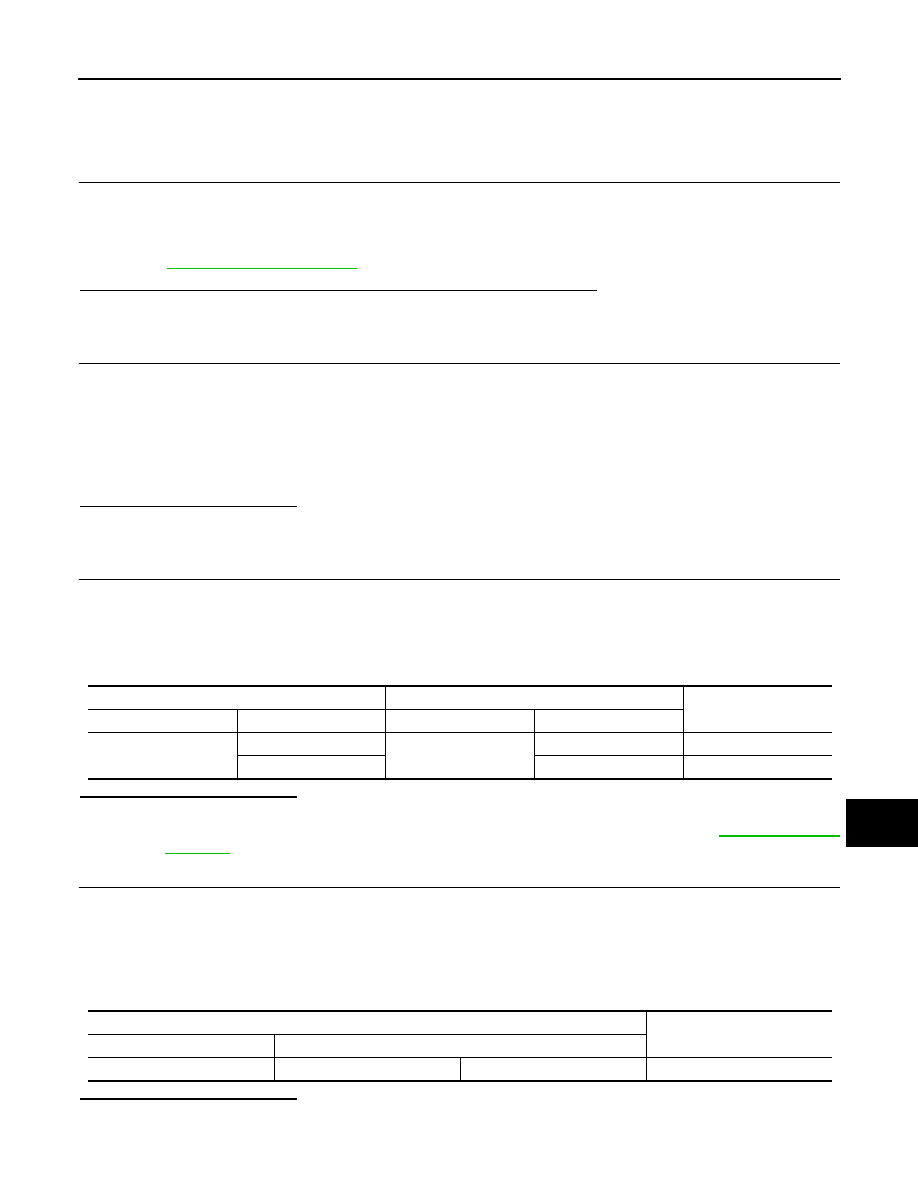
Check the continuity between the ADAS control unit harness connector terminals.
Is the inspection result normal?
YES
>> GO TO 5.
NO
>> Check the harness and repair the root cause.
ADAS control unit harness connector
ICC sensor harness connector
Continuity
Connector No.
Terminal No.
Connector No.
Terminal No.
B61
7
E65
3
Existed
8
6
Existed
ADAS control unit harness connector
Continuity
Connector No.
Terminal No.
B61
7
8
Not existed