Infiniti QX56 (Z62). Manual - part 871


  Index      Infiniti     Infiniti QX56 (Z62) - service repair manual 2011 year


Search            


Content   ..  869  870  871  872   ..


Infiniti QX56 (Z62). Manual - part 871


LAN

MAIN LINE BETWEEN DLC AND E-SUS CIRCUIT

LAN-61

< DTC/CIRCUIT DIAGNOSIS >

[CAN]

C

D

E

F

G

H

I

J

K

L

B

A

O

P

N

MAIN LINE BETWEEN DLC AND E-SUS CIRCUIT

Diagnosis Procedure

INFOID:0000000006238655

1.

CHECK CONNECTOR

1.

Turn the ignition switch OFF.

2.

Disconnect the battery cable from the negative terminal.

3.

Check the following terminals and connectors for damage, bend and loose connection (connector side
and harness side).

-

Harness connector M19

-

Harness connector B2

Is the inspection result normal?

YES

>> GO TO 2.

NO

>> Repair the terminal and connector.

2.

CHECK HARNESS CONTINUITY (OPEN CIRCUIT)

1.

Disconnect the harness connectors M19 and B2.

2.

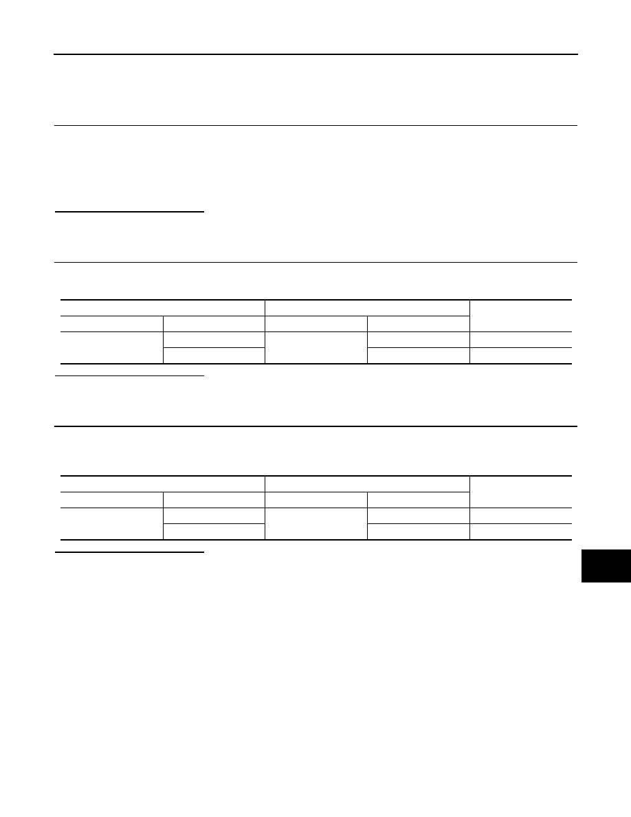
Check the continuity between the data link connector and the harness connector.

Is the inspection result normal?

YES

>> GO TO 3.

NO

>> Repair the main line between the data link connector and the harness connector M19.

3.

CHECK HARNESS CONTINUITY (OPEN CIRCUIT)

1.

Disconnect the connector of air levelizer control module.

2.

Check the continuity between the harness connector and the air levelizer control module harness connec-
tor.

Is the inspection result normal?

YES (Present error)>>Check CAN system type decision again.
YES (Past error)>>Error was detected in the main line between the data link connector and the air levelizer

control module. 

NO

>> Repair the main line between the harness connector B2 and the air levelizer control module.

Data link connector

Harness connector

Continuity

Connector No.

Terminal No.

Connector No.

Terminal No.

M4

6

M19

29

Existed

14

30

Existed

Harness connector

Air levelizer control module harness connector

Continuity

Connector No.

Terminal No.

Connector No.

Terminal No.

B2

29

B84

16

Existed

30

7

Existed

LAN-62

< DTC/CIRCUIT DIAGNOSIS >

[CAN]

MAIN LINE BETWEEN E-SUS AND ADP CIRCUIT

MAIN LINE BETWEEN E-SUS AND ADP CIRCUIT

Diagnosis Procedure

INFOID:0000000006238656

1.

CHECK HARNESS CONTINUITY (OPEN CIRCUIT)

1.

Turn the ignition switch OFF.

2.

Disconnect the battery cable from the negative terminal.

3.

Disconnect the following harness connectors.

-

ECM

-

Air levelizer control module

-

Harness connectors B24 and B460

4.

Check the continuity between the air levelizer control module harness connector and the harness connec-
tor.

Is the inspection result normal?

YES (Present error)>>Check CAN system type decision again.
YES (Past error)>>Error was detected in the main line between the air levelizer control module and the driver

seat control unit. 

NO

>> Repair the main line between the air levelizer control module and the harness connector B24.

Air levelizer control module harness connector

Harness connector

Continuity

Connector No.

Terminal No.

Connector No.

Terminal No.

B84

16

B24

13

Existed

7

12

Existed

LAN

MAIN LINE BETWEEN ADP AND PWBD CIRCUIT

LAN-63

< DTC/CIRCUIT DIAGNOSIS >

[CAN]

C

D

E

F

G

H

I

J

K

L

B

A

O

P

N

MAIN LINE BETWEEN ADP AND PWBD CIRCUIT

Diagnosis Procedure

INFOID:0000000006220540

1.

CHECK HARNESS CONTINUITY (OPEN CIRCUIT)

1.

Turn the ignition switch OFF.

2.

Disconnect the battery cable from the negative terminal.

3.

Disconnect the following harness connectors.

-

CAN gateway

-

Harness connectors B460 and B24

-

Automatic back door control module

4.

Check the continuity between the harness connector and the automatic back door control module harness
connector.

Is the inspection result normal?

YES (Present error)>>Check CAN system type decision again.
YES (Past error)>>Error was detected in the main line between the driver seat control unit and the automatic

back door control module. 

NO

>> Repair the main line between the harness connector B24 and the automatic back door control

module.

Harness connector

Automatic back door control module

harness connector

Continuity

Connector No.

Terminal No.

Connector No.

Terminal No.

B24

13

B26

7

Existed

12

6

Existed

LAN-64

< DTC/CIRCUIT DIAGNOSIS >

[CAN]

MAIN LINE BETWEEN RDR-R AND RDR-L CIRCUIT

MAIN LINE BETWEEN RDR-R AND RDR-L CIRCUIT

Diagnosis Procedure

INFOID:0000000006220541

1.

CHECK CONNECTOR

1.

Turn the ignition switch OFF.

2.

Disconnect the battery cable from the negative terminal.

3.

Check the following terminals and connectors for damage, bend and loose connection (connector side
and harness side).

-

Harness connector B239

-

Harness connector B63

Is the inspection result normal?

YES

>> GO TO 2.

NO

>> Repair the terminal and connector.

2.

CHECK HARNESS CONTINUITY (OPEN CIRCUIT)

1.

Disconnect the following harness connectors.

-

Side radar RH

-

Harness connectors B239 and B63

2.

Check the continuity between the side radar RH harness connector and the harness connector.

Is the inspection result normal?

YES

>> GO TO 3.

NO

>> Repair the main line between the side radar RH and the harness connector B239.

3.

CHECK HARNESS CONTINUITY (OPEN CIRCUIT)

1.

Disconnect the connector of side radar LH.

2.

Check the continuity between the harness connector and the side radar LH harness connector.

Is the inspection result normal?

YES (Present error)>>Check CAN system type decision again.
YES (Past error)>>Error was detected in the main line between the side radar RH and the side radar LH. 
NO

>> Repair the main line between the harness connector B63 and the side radar LH.

Side radar RH harness connector

Harness connector

Continuity

Connector No.

Terminal No.

Connector No.

Terminal No.

B243

4

B239

7

Existed

3

3

Existed

Harness connector

Side radar LH harness connector

Continuity

Connector No.

Terminal No.

Connector No.

Terminal No.

B63

7

B74

4

Existed

3

3

Existed


Content   ..  869  870  871  872   ..