Infiniti QX56 (Z62). Manual - part 838
INL-82
< SERVICE DATA AND SPECIFICATIONS (SDS)
SERVICE DATA AND SPECIFICATIONS (SDS)
SERVICE DATA AND SPECIFICATIONS (SDS)
SERVICE DATA AND SPECIFICATIONS (SDS)
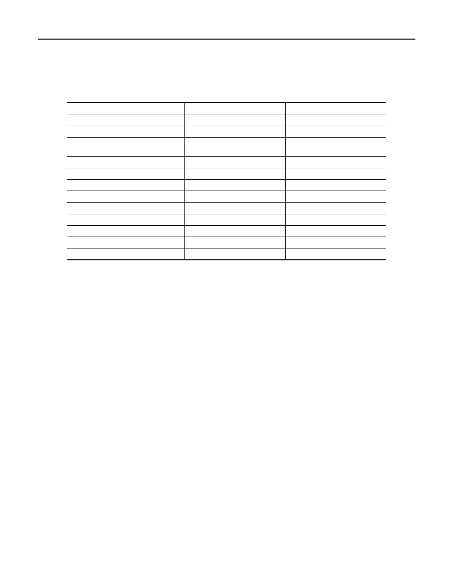
Bulb Specifications
INFOID:0000000006288670
Item
Type
Wattage (W)
Push-button ignition switch illumination
LED
—
Map lamp
Wedge
8
Console lamp
(integrated into the map lamp assembly)
LED
—
Puddle lamp
LED
—
Vanity mirror lamp
—
2
Glove box lamp
Wedge
1.4
Foot lamp (driver and passenger)
Wedge
1.4
Rear foot lamp
LED
—
Mood lamp (front and rear door armrest)
LED
—
Step lamp
Wedge
8
Personal lamp
Wedge
8
Luggage room lamp
—
8