Infiniti QX56 (Z62). Manual - part 717
FRONT BUMPER
EXT-15
< REMOVAL AND INSTALLATION >
C
D
E
F
G
H
I
J
L
M
A
B
EXT
N
O
P
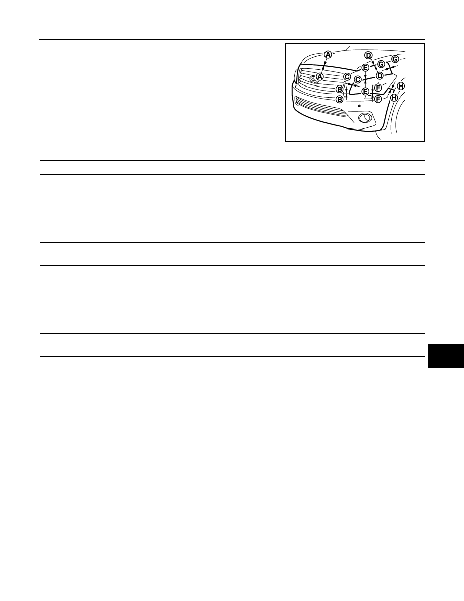
• The following table shows the specified values for checking normal
installation status.
• Fitting adjustment cannot be performed.
JMKIA5454ZZ
Portion
Clearance
Surface height difference
Front grille –
Hood
A – A
3.7 – 8.3 mm
(0.146 – 0.327 in)
(-0.9) – (+3.9) mm
[(-0.035) – (+0.154) in]
Bumper fascia assembly –
Front bumper molding
B – B
0.1 – 3.4 mm
(0.004 – 0.134 in)
(-1.9) – (+1.9) mm
[(-0.075) – (+0.075) in]
Front bumper molding –
Headlamp
C – C
0.1 – 2.5 mm
(0.004 – 0.098 in)
—
Front bumper molding –
Hood
D – D
1.2 – 5.8 mm
(0.047 – 0.228 in)
(-2.4) – (+2.4) mm
[(-0.094) – (+0.094)]
Front bumper molding–
Headlamp
E – E
0.1 – 2.5 mm
(0.004 – 0.098 in)
—
Bumper fascia assembly –
Headlamp
F – F
0.2 – 3.1 mm
(0.008 – 0.122 in)
0.5 – 3.5 mm
(0.020 – 0.138 in)
Front fender –
Front bumper molding
G – G
0.0 – 0.7 mm
(0.000 – 0.028 in)
(-1.0) – (+1.0) mm
[(-0.039) – (+0.039) in]
Front fender –
Bumper fascia assembly
H – H
0.0 – 0.8 mm
(0.000 – 0.031 in)
(-0.7) – (+1.3) mm
[(-0.028) – (+0.051) in]