Infiniti QX56 (Z62). Manual - part 683


  Index      Infiniti     Infiniti QX56 (Z62) - service repair manual 2011 year


Search            


Content   ..  681  682  683  684   ..


Infiniti QX56 (Z62). Manual - part 683


EXL-24

< SYSTEM DESCRIPTION >

[XENON TYPE]

DIAGNOSIS SYSTEM (BCM)

*

1

: Factory setting

*

2

: For models for Canada, this item is displayed but is not operated.
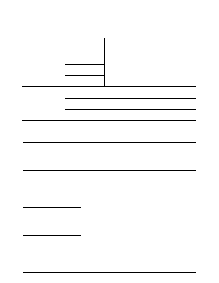
DATA MONITOR

BATTERY SAVER SET

On*

1

With the exterior lamp battery saver function

Off

Without the exterior lamp battery saver function

ILL DELAY SET

MODE 1*

1

45 sec.

Sets delay timer function timer operation time
(All doors closed)

MODE 2

Without the 
function

MODE 3

30 sec.

MODE 4

60 sec.

MODE 5

90 sec.

MODE 6

120 sec.

MODE 7

150 sec.

MODE 8

180 sec.

AUTO LIGHT LOGIC SET*

2

MODE 1*

1

With twilight ON custom & with wiper INT, LO and HI

MODE 2

With twilight ON custom & with wiper LO and HI

MODE 3

With twilight ON custom & without

MODE 4

Without twilight ON custom & with wiper INT, LO and HI

MODE 5

Without twilight ON custom & with wiper LO and HI

MODE 6

Without twilight ON custom & without

Service item

Setting item

Setting

Monitor item

[Unit]

Description

PUSH SW
[On/Off]

The switch status input from push-button ignition switch

ENGINE STATE
[Stop/Stall/Crank/Run]

The engine status received from ECM via CAN communication

VEH SPEED 1
[km/h]

The value of the vehicle speed received from combination meter via CAN communi-
cation

TURN SIGNAL R
[On/Off]

Each switch status that BCM judges from the combination switch reading function

TURN SIGNAL L
[On/Off]

TAIL LAMP SW
[On/Off]

HI BEAM SW
[On/Off]

HEAD LAMP SW1
[On/Off]

HEAD LAMP SW2
[On/Off]

PASSING SW
[On/Off]

AUTO LIGHT SW
[On/Off]

FR FOG SW
[On/Off]

RR FOG SW
[On/Off]

NOTE:
This item is indicated, but can not monitored

DIAGNOSIS SYSTEM (BCM)

EXL-25

< SYSTEM DESCRIPTION >

[XENON TYPE]

C

D

E

F

G

H

I

J

K

M

A

B

EXL

N

O

P

ACTIVE TEST

*: Only models for Canada display this item.

FLASHER

FLASHER : CONSULT-III Function (BCM - FLASHER)

INFOID:0000000006213912

WORK SUPPORT

DOOR SW-DR
[On/Off]

The switch status input from front door switch (driver side)

DOOR SW-AS
[On/Off]

The switch status input from front door switch (passenger side)

DOOR SW-RR
[On/Off]

The switch status input from rear door switch RH

DOOR SW- RL
[On/Off]

The switch status input from rear door switch LH

DOOR SW-BK
[On/Off]

The switch status input from back door switch

OPTICAL SENSOR
[On/Off]

The sensor status input from optical sensor

OPTI SEN (DTCT)
[V]

The value of outside brightness voltage input from the optical sensor

OPTI SEN (FILT)
[V]

The value of outside brightness voltage filtered by BCM

Monitor item

[Unit]

Description

Test item

Operation

Description

TAIL LAMP

On

Transmits the position light request signal to IPDM E/R via CAN commu-
nication to turn the tail lamp ON

Off

Stops the tail lamp request signal transmission

HEAD LAMP

Hi

Transmits the high beam request signal via CAN communication to turn 
the headlamp (HI)

Lo

Transmits the low beam request signal via CAN communication to turn 
the headlamp (LO)

Off

Stops the high & low beam request signal transmission

FR FOG LAMP

On

Transmits the front fog lights request signal to IPDM E/R via CAN com-
munication to turn the front fog lamp ON

Off

Stops the front light request signal transmission

RR FOG LAMP

On

NOTE:
This item is indicated, but can not tested

Off

DAYTIME RUNNING LIGHT*

On

Transmits the front fog lights request signal to IPDM E/R via CAN com-
munication to turn the front fog lamp ON (daytime running light system)

Off

Stops the front light request signal transmission (daytime running light 
system)

ILL DIM SIGNAL

On

• Transmits the dimmer signal to combination meter via CAN communi-

cation and dims combination meter

• Transmits the dimmer signal to AV control unit and dims display

Off

Stops the dimmer signal transmission

EXL-26

< SYSTEM DESCRIPTION >

[XENON TYPE]

DIAGNOSIS SYSTEM (BCM)

*: Factory setting

DATA MONITOR

ACTIVE TEST

Service item

Setting item

Setting

HAZARD ANSWER 
BACK

Lock Only

With locking only

Sets the hazard warning lamp answer back function 
when the door is lock/unlock with the request switch or 
the key fob.

Unlk Only

With unlocking only

Lock&Unlk

*

With locking/unlocking

Off

Without the function

Monitor item

[Unit]

Description

REQ SW-DR
[On/Off]

The switch status input from the request switch (driver side)

REQ SW-AS
[On/Off]

The switch status input from the request switch (passenger side)

PUSH SW
[On/Off]

The switch status input from the push-button ignition switch

TURN SIGNAL R
[On/Off]

Each switch status that BCM detects from the combination switch reading function

TURN SIGNAL L
[On/Off]

HAZARD SW
[On/Off]

The switch status input from the hazard switch

RKE-LOCK
[On/Off]

Lock signal status received from the remote keyless entry receiver

RKE-UNLOCK
[On/Off]

Unlock signal status received from the remote keyless entry receiver

RKE-PANIC
[On/Off]

Panic alarm signal status received from the remote keyless entry receiver

Test item

Operation

Description

FLASHER

RH

Outputs the voltage to blink the right side turn signal lamps.

LH

Outputs the voltage to blink the left side turn signal lamps.

Off

Stops the voltage to turn the turn signal lamps OFF.

DIAGNOSIS SYSTEM (IPDM E/R)

EXL-27

< SYSTEM DESCRIPTION >

[XENON TYPE]

C

D

E

F

G

H

I

J

K

M

A

B

EXL

N

O

P

DIAGNOSIS SYSTEM (IPDM E/R)

Diagnosis Description

INFOID:0000000006368066

AUTO ACTIVE TEST

Description

In auto active test, the IPDM E/R sends a drive signal to the following systems to check their operation.
• Oil pressure warning lamp
• Rear window defogger
• Front wiper (LO, HI)
• Parking lamp
• License plate lamp
• Tail lamp
• Side marker lamp
• Front fog lamp
• Headlamp (LO, HI)
• A/C compressor (magnet clutch)

Operation Procedure

CAUTION:

Never perform auto active test in the following conditions.
• Engine is running.
• CONSULT-III is connected.

1.

Close the hood and lift the wiper arms from the windshield. (Prevent windshield damage due to wiper
operation)
NOTE:
When auto active test is performed with hood opened, sprinkle water on windshield beforehand.

2.

Turn the ignition switch OFF.

3.

Turn the ignition switch ON, and within 20 seconds, press the driver door switch 10 times. Then turn the
ignition switch OFF.

CAUTION:

Close passenger door.

4.

Turn the ignition switch ON within 10 seconds. After that the horn sounds once and the auto active test
starts.

CAUTION:

Engine starts when ignition switch is turned ON while brake pedal is depressed.

5.

The oil pressure warning lamp starts blinking when the auto active test starts.

6.

After a series of the following operations is repeated 3 times, auto active test is completed.

NOTE:
• When auto active test has to be cancelled halfway through test, turn the ignition switch OFF.
• When auto active test is not activated, door switch may be the cause. Check door switch. Refer to 

DLK-117,

"Component Function Check"

.

Inspection in Auto Active Test

When auto active test is actuated, the following operation sequence is repeated 3 times.

Operation 
sequence

Inspection location

Operation

1

Oil pressure warning lamp

Blinks continuously during operation of auto active test 

2

Rear window defogger

10 seconds

3

Front wiper

LO for 5 seconds 

 HI for 5 seconds

4

• Parking  lamp
• License plate lamp
• Tail lamp
• Side marker lamp
• Front fog lamp

10 seconds


Content   ..  681  682  683  684   ..