Infiniti QX56 (Z62). Manual - part 658
EM-72
< REMOVAL AND INSTALLATION >
TIMING CHAIN
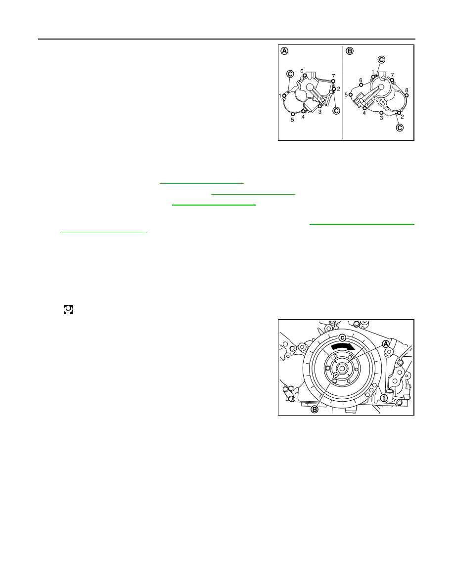
d.
Being careful not to move seal ring from the installation groove,
align dowel pins on front cover with dowel pin holes (C) to install
valve timing control covers.
e.
Tighten mounting bolts in numerical order as shown in the fig-
ure.
14. Install camshaft position sensor and valve timing control solenoid valve (RH and LH) to valve timing con-
trol cover, if removed.
• Be sure to tighten mounting bolts with flanges completely seated.
15. Install oil pan (upper). Refer to
16. Install oil pan (lower) and oil strainer. Refer to
17. Install water pump pulley. Refer to
.
18. Install crankshaft pulley.
• Fix the crankshaft as instructed in the removal procedure. Refer to
a.
Install crankshaft pulley, taking care not to damage front oil seal.
b.
Apply engine oil onto threaded parts of crankshaft pulley bolt and seating area.
• Lightly tapping its center with plastic hammer, insert crankshaft pulley.
CAUTION:
Never tap crankshaft pulley on the side surface where belt is installed (outer circumference).
c.
Tighten crankshaft pulley bolt.
d.
Put a paint mark (A) on crankshaft pulley (1) aligning with angle
mark (B) on crankshaft pulley bolt.
e.
Tighten crankshaft pulley bolt (clockwise).
• Check the tightening angle by referencing to the notches. The
angle between two notches is 90 degrees.
19. Rotate crankshaft pulley in normal direction (clockwise when viewed from engine front) to confirm it turns
smoothly.
20. Install in the reverse order of removal.
Inspection
INFOID:0000000006289567
INSPECTION AFTER DISASSEMBLY
Timing Chain
A
: Bank 2
B
: Bank 1
JPBIA3476ZZ
: 205 N·m (21 kg-m, 151 ft-lb)
Angle tightening: 90 degrees (c)
JPBIA2066ZZ