Infiniti QX56 (Z62). Manual - part 579
EC-294
< DTC/CIRCUIT DIAGNOSIS >
[VK56VD]
P0300, P0301, P0302, P0303, P0304, P0305, P0306, P0307, P0308 MISFIRE
When the gap is less than 13 mm (0.52 in), a spark might be generated even if the coil is malfunc-
tioning.
Is the inspection result normal?
YES
>> GO TO 9.
NO
>> GO TO 6.
6.
CHECK FUNCTION OF IGNITION COIL-II
1.
Turn ignition switch OFF.
2.
Disconnect spark plug and connect a non-malfunctioning spark plug.
3.
Crank engine for approximately 3 seconds, and recheck whether spark is generated between the spark
plug and the grounded metal portion.
Is the inspection result normal?
YES
>> GO TO 7.
NO
>> Check ignition coil, power transistor and their circuits. Refer to
.
7.
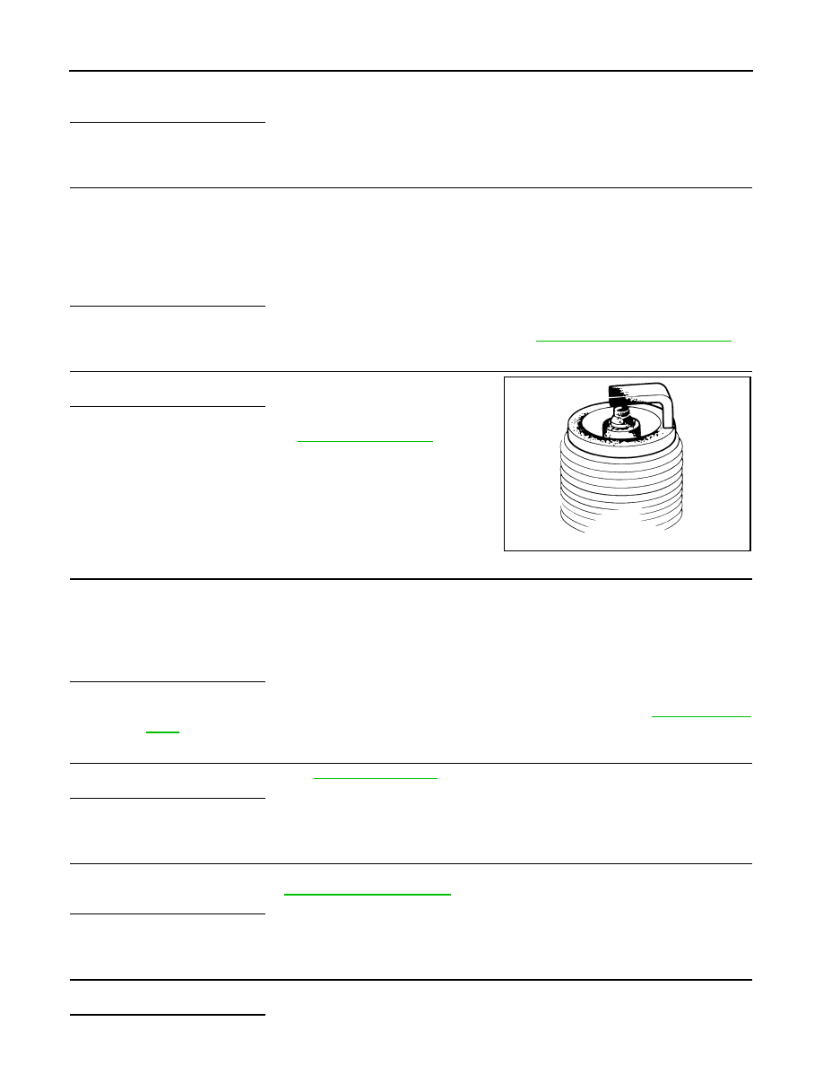
CHECK SPARK PLUG
Check the initial spark plug for fouling, etc.
Is the inspection result normal?
YES
>> Replace spark plug(s) with standard type one(s). For
spark plug type, refer to
.
NO
>> Repair or clean spark plug. Then GO TO 8.
8.
CHECK FUNCTION OF IGNITION COIL-III
1.
Reconnect the initial spark plugs.
2.
Crank engine for approximately 3 seconds, and recheck whether spark is generated between the spark
plug and the grounded portion.
Is the inspection result normal?
YES
>> INSPECTION END
NO
>> Replace spark plug(s) with standard type one(s). For spark plug type, refer to
.
9.
CHECK COMPRESSION PRESSURE
Check compression pressure. Refer to
.
Is the inspection result normal?
YES
>> GO TO 10.
NO
>> Check pistons, piston rings, valves, valve seats and cylinder head gaskets.
10.
CHECK FUEL PRESSURE
1.
Install all removed parts.
2.
Check fuel pressure. Refer to
Is the inspection result normal?
YES
>> GO TO 12.
NO
>> GO TO 11.
11.
DETECT MALFUNCTIONING PART
Check fuel hoses and fuel tubes for clogging.
Is the inspection result normal?
Spark should be generated.
SEF156I
Spark should be generated.