Infiniti QX56 (Z62). Manual - part 548


  Index      Infiniti     Infiniti QX56 (Z62) - service repair manual 2011 year


Search            


Content   ..  546  547  548  549   ..


Infiniti QX56 (Z62). Manual - part 548


EC-170

< DTC/CIRCUIT DIAGNOSIS >

[VK56VD]

POWER SUPPLY AND GROUND CIRCUIT

Check the following.
• Loose or poor connection for each connector and harness
• Harness for open or short between ECM and IPDM E/R

>> Repair open circuit, short to ground or short to power in harness or connectors.

11.

CHECK 20 A FUSE

1.

Disconnect 20 A fuse (No. 43) from IPDM E/R.

2.

Check 20 A fuse.

Is the inspection result normal?

YES

>> GO TO 14.

NO

>> Replace 15 A fuse.

12.

CHECK ECM POWER SUPPLY CIRCUIT-VI

1.

Disconnect ECM harness connector.

2.

Disconnect IPDM E/R harness connector.

3.

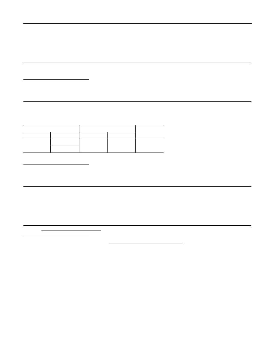
Check the continuity between ECM harness connector and IPDM E/R harness connector.

4.

Also check harness for short to ground and short to power.

Is the inspection result normal?

YES

>> GO TO 14.

NO

>> GO TO 13.

13.

DETECT MALFUNCTIONING PART

Check the following.
• Loose or poor connection for each connector and harness
• Harness for open or short between ECM and IPDM E/R

>> Repair open circuit, short to ground or short to power in harness or connectors.

14.

CHECK INTERMITTENT INCIDENT

Refer to 

GI-40, "Intermittent Incident"

.

Is the inspection result normal?

YES

>> Replace IPDM E/R. Refer to 

PCS-32, "Removal and Installation"

.

NO

>> Repair open circuit, short to ground or short to power in harness or connectors.

ECM

IPDM E/R

Continuity

Connector

Terminal

Connector

Terminal

E80

171

E14

35

Existed

172

U0101 CAN COMM CIRCUIT

EC-171

< DTC/CIRCUIT DIAGNOSIS >

[VK56VD]

C

D

E

F

G

H

I

J

K

L

M

A

EC

N

P

O

U0101 CAN COMM CIRCUIT

DTC Logic

INFOID:0000000006217764

DTC DETECTION LOGIC

DTC CONFIRMATION PROCEDURE

1.

PERFORM DTC CONFIRMATION PROCEDURE

1.

Turn ignition switch ON and wait at least 3 seconds.

2.

Check DTC.

Is DTC detected?

YES

>>

EC-171, "Diagnosis Procedure"

.

NO

>> INSPECTION END

Diagnosis Procedure

INFOID:0000000006217765

Perform the trouble diagnosis for CAN communication system. Refer to 

LAN-18, "Trouble Diagnosis Flow

Chart"

.

DTC No.

Trouble diagnosis name

(Trouble diagnosis content)

DTC detecting condition

Possible cause

U0101

LOST COMM (TCM)
(Lost communication with TCM)

When ECM is not transmitting or receiving 
CAN communication signal of OBD (emis-
sion related diagnosis) with TCM for 2 sec-
onds or more.

• CAN communication line betrween 

TCM and ECM
(CAN communication line is open or 
shorted)

EC-172

< DTC/CIRCUIT DIAGNOSIS >

[VK56VD]

U1001 CAN COMM CIRCUIT

U1001 CAN COMM CIRCUIT

DTC Logic

INFOID:0000000006217768

DTC DETECTION LOGIC

DTC CONFIRMATION PROCEDURE

1.

PERFORM DTC CONFIRMATION PROCEDURE

1.

Turn ignition switch ON and wait at least 3 seconds.

2.

Check 1st trip DTC.

Is 1st trip DTC detected?

YES

>>

EC-172, "Diagnosis Procedure"

.

NO

>> INSPECTION END

Diagnosis Procedure

INFOID:0000000006217769

Perform the trouble diagnosis for CAN communication system. Refer to 

LAN-18, "Trouble Diagnosis Flow

Chart"

.

DTC No.

Trouble diagnosis name

(Trouble diagnosis content)

DTC detecting condition

Possible cause

U1001

CAN COMM CIRCUIT
(CAN communication line)

When ECM is not transmitting or receiving 
CAN communication signal other than OBD 
(emission related diagnosis) for 2 seconds 
or more.

• Harness or connectors

(CAN communication line is open or 
shorted)

U0113, U1003 CAN COMM CIRCUIT

EC-173

< DTC/CIRCUIT DIAGNOSIS >

[VK56VD]

C

D

E

F

G

H

I

J

K

L

M

A

EC

N

P

O

U0113, U1003 CAN COMM CIRCUIT

DTC Logic

INFOID:0000000006412037

DTC DETECTION LOGIC

NOTE:
If DTC U0113 or U1003 is displayed with DTC P0607, first perform the trouble diagnosis for DTC P0607.
Refer to 

EC-378, "DTC Logic"

.

DTC CONFIRMATION PROCEDURE

1.

PRECONDITIONING

TESTING CONDITION:
Before performing the following procedure, confirm that battery voltage is 10 V or more at idle.

>> GO TO 2.

2.

PERFORM DTC CONFIRMATION PROCEDURE

1.

Turn ignition switch ON and wait at least 3 seconds.

2.

Check DTC.

Is DTC detected?

YES

>> Proceed to 

EC-173, "Diagnosis Procedure"

.

NO

>> INSPECTION END

Diagnosis Procedure

INFOID:0000000006412038

1.

CHECK VVEL CAN COMMUNICATION CIRCUIT

1.

Turn ignition switch OFF.

2.

Disconnect ECM harness connector.

3.

Disconnect VVEL control module harness connector.

4.

Check the continuity between ECM harness connector and VVEL control module harness connector.

5.

Also check harness for short to ground and short to power.

Is the inspection result normal?

YES

>> GO TO 3.

NO

>> GO TO 2.

2.

DETECT MALFUNCTIONING PART

Check the following.
• Harness for open or short between ECM and VVEL control module
• Loose or poor connection for each connector and harness

DTC No.

Trouble diagnosis name

(Trouble diagnosis content)

DTC detecting condition

Possible cause

U0113

CAN COMM CIRCUIT
(Lost communication with VVEL 
control module)

When ECM is not transmitting or receiving 
CAN communication signal of OBD (emis-
sion related diagnosis) with VVEL control 
module for 2 seconds or more.

• Harness or connectors

(VVEL CAN communication line is 
open or shorted)

• ECM
• VVEL control module

U1003

When ECM is not transmitting or receiving 
CAN communication signal other than OBD 
(emission related diagnosis) with VVEL 
control module for 2 seconds or more.

ECM

VVEL control module

Continuity

Connector

Terminal

Connector

Terminal

E80

161

F56

24

Existed

166

11


Content   ..  546  547  548  549   ..