Infiniti QX56 (Z62). Manual - part 528
EC-90
< ECU DIAGNOSIS INFORMATION >
[VK56VD]
ECM
111
(R)
175
(B)
Fuel injector driver power supply
Input
[Ignition switch: ON]
BATTERY VOLTAGE
(11 - 14 V)
112
(SB)
175
(B)
Fuel injector driver power supply
Input
[Ignition switch: ON]
BATTERY VOLTAGE
(11 - 14 V)
114
(B)
—
ECM ground
—
—
—
115
(B)
—
ECM ground
—
—
—
120
(Y)
175
(B)
EVAP canister vent control valve
Output
[Ignition switch: ON]
BATTERY VOLTAGE
(11 - 14 V)
122
(BR/
W)
175
(B)
VVEL actuator motor relay abort
signal (VVEL control module)
Input
[Ignition switch: ON]
0 V
123
(V/R)
175
(B)
Throttle control motor relay
Output
[Ignition switch: ON
→
OFF]
0 - 1.0 V
↓
BATTERY VOLTAGE
(11 - 14 V)
↓
0 V
[Ignition switch: ON]
0 - 1.0 V
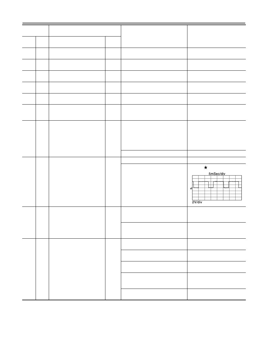
125
(GR)
175
(B)
Fuel pump control module
(FPCM)
Output
[When cranking engine]
0 - 0.5 V
[Engine is running]
• Warm-up condition
0 - 4.0 V
126
(O)
129
(P/L)
Accelerator pedal position sen-
sor 2
Input
[Ignition switch: ON]
• Engine: Stopped
• Accelerator pedal: Fully released
0.28 - 0.48 V
[Ignition switch: ON]
• Engine: Stopped
• Accelerator pedal: Fully depressed
2.0 - 2.5 V
128
(Y)
130
(R)
ASCD steering switch
Input
[Ignition switch: ON]
• ASCD steering switch: OFF
4 V
[Ignition switch: ON]
• MAIN switch: Pressed
0 V
[Ignition switch: ON]
• CANCEL switch: Pressed
1 V
[Ignition switch: ON]
• RESUME/ACCELERATE switch:
Pressed
3 V
[Ignition switch: ON]
• SET/COAST switch: Pressed
2 V
Terminal No.
(Wire color)
Description
Condition
Value
(Approx.)
+
–
Signal name
Input/
Output
JPBIA3344ZZ