Infiniti QX56 (Z62). Manual - part 502
DLN-208
< UNIT DISASSEMBLY AND ASSEMBLY >
[REAR FINAL DRIVE: R230]
DIFFERENTIAL ASSEMBLY
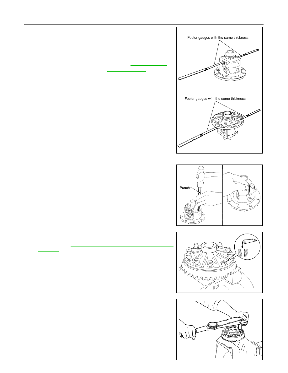
b.
Using feeler gauge, measure the clearance between side gear
back and differential case at 3 different points, while rotating
side gear. Average the 3 readings, and then measure the clear-
ance of the other side as well.
CAUTION:
To prevent side gear from tilting, insert feeler gauges with
the same thickness from both sides.
c.
If the back clearance is outside the specification, use a thicker/
thinner side gear thrust washer to adjust. For selecting thrust
washer, refer to the latest parts information.
CAUTION:
Select a side gear thrust washer for right and left individu-
ally.
6.
Drive a lock pin into pinion mate shaft, using a punch.
Make sure lock pin is flush with differential case.
CAUTION:
Never reuse lock pin.
7.
Apply thread locking sealant into the thread hole of drive gear.
• Use Genuine High Strength Thread Locking Sealant or equiv-
alent. Refer to
GI-22, "Recommended Chemical Products and
.
CAUTION:
Clean and degrease drive gear back and threaded holes
sufficiently.
8.
Install drive gear to differential case.
CAUTION:
Align the matching marks of differential case and drive
gear.
9.
Tighten the mounting bolts with the following procedure.
CAUTION:
Apply anti-corrosin oil to the thread and seat of mounting
bolts.
a.
Tighten the bolts in a crisscross fashion to the specified torque.
b.
Tighten the bolts additionally to the specified angle.
Standard
Side gear back clearance
: Refer to
.
When the back clearance
is large:
Use a thicker thrust wash-
er.
When the back clearance
is small:
Use a thinner thrust wash-
er.
PDIA0576E
SPD030
SDIA2594E
Drive gear mounting
bolts tightening torque
: 78.5 N•m (8.0 kg-m, 58 ft-lb)
SDIA0247J