Infiniti QX56 (Z62). Manual - part 479
DLN-116
< REMOVAL AND INSTALLATION >
[TRANSFER: ATX90A]
TRANSFER HI-LO POSITION SENSOR
TRANSFER HI-LO POSITION SENSOR
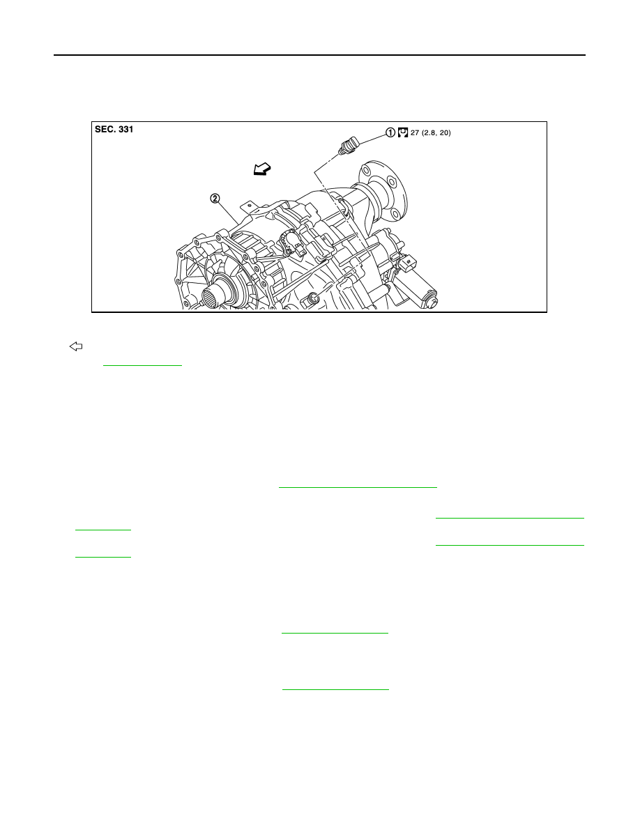
Exploded View
INFOID:0000000006222337
Removal and Installation
INFOID:0000000006222338
REMOVAL
1.
Turn the ignition switch OFF.
2.
Disconnect negative battery terminal.
CAUTION:
Wait for 5 seconds after turning ignition switch OFF.
3.
Remove exhaust front tube (LH). Refer to
EX-5, "Removal and Installation"
4.
Support transfer assembly and transmission assembly with a jack.
5.
Remove front suspension rear cross member with a power tool. Refer to
.
6.
Remove rear engine mounting cross member with a power tool. Refer to
.
7.
Remove heat insulator of exhaust front tube (LH).
8.
Lower jack to the position where the transfer Hi-Lo position sensor can be removed.
9.
Disconnect the transfer Hi-Lo position sensor connector.
10. Remove the transfer Hi-Lo position sensor.
11. Perform inspection after removal. Refer to
INSTALLATION
Note the following, and install in the reverse order of removal.
• Never damage O-ring of transfer Hi-Lo position sensor.
• Perform inspection after installation. Refer to
Inspection
INFOID:0000000006222339
INSPECTION AFTER REMOVAL
Check the O-ring assembled transfer Hi-Lo position sensor for wear, crack and damage. Replace the transfer
Hi-Lo position sensor if there is malfunction.
INSPECTION AFTER INSTALLATION
After driving, check the surface fitting transfer Hi-Lo position sensor to transfer assembly for fluid leakage.
1.
Transfer Hi-Lo position sensor
2.
Transfer assembly
: Vehicle front
Refer to
for symbols not described above.
JPDIE0282GB