Infiniti QX56 (Z62). Manual - part 424


  Index      Infiniti     Infiniti QX56 (Z62) - service repair manual 2011 year


Search            


Content   ..  422  423  424  425   ..


Infiniti QX56 (Z62). Manual - part 424


DLK-162

< DTC/CIRCUIT DIAGNOSIS >

BACK DOOR CLOSURE MOTOR

BACK DOOR CLOSURE MOTOR

Diagnosis Procedure

INFOID:0000000006225989

1.

CHECK BACK DOOR CLOSURE MOTOR INPUT SIGNAL

1.

Turn ignition switch OFF.

2.

Disconnect back door lock assembly connector.

3.

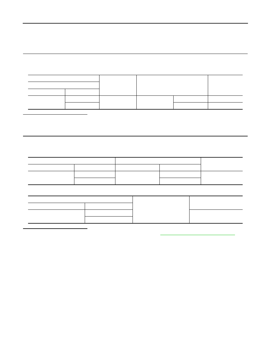
Check voltage between back door lock assembly harness connector and ground. 

Is the inspection result normal?

YES

>> Replace back door lock assembly.

NO

>> GO TO 2.

2.

CHECK BACK DOOR CLOSURE MOTOR CIRCUIT

1.

Disconnect automatic back door control module connector.

2.

Check continuity between automatic back door control module harness connector and back door lock
assembly harness connector. 

3.

Check continuity between automatic back door control module harness connector and ground.

Is the inspection result normal?

YES

>> Replace automatic back door control module. Refer to 

DLK-262, "Removal and Installation"

.

NO

>> Repair or replace harness.

(+)

(–)

Condition

Voltage

(Approx.) 

Back door lock assembly

 Connector

Terminal

D157

1

Ground

Back door opener 
switch

Pressed

Battery voltage

2

Released

0  V

Automatic back door control module

Back door lock assembly

Continuity 

 Connector

Terminal

 Connector

Terminal

B26

11

D157

1

Existed

12

2

Automatic back door control module

Ground

Continuity 

 Connector

Terminal

B26

11

Not existed

12

AUTOMATIC BACK DOOR WARNING BUZZER

DLK-163

< DTC/CIRCUIT DIAGNOSIS >

C

D

E

F

G

H

I

J

L

M

A

B

DLK

N

O

P

AUTOMATIC BACK DOOR WARNING BUZZER

Diagnosis Procedure

INFOID:0000000006225990

1.

CHECK FUSE

1.

Turn ignition switch OFF.

2.

Check 10 A fuse, [No.9, located in fuse block (J/B)].

Is the inspection result normal?

YES

>> GO TO 2.

NO

>> Replace the blown fuse after repairing the affected circuit if a fuse is blown.

2.

CHECK AUTOMATIC BACK DOOR WARNING BUZZER POWER SUPPLY CIRCUIT

1.

Disconnect automatic back door warning buzzer connector.

2.

Check voltage between automatic back door warning buzzer harness connector and ground.

Is the inspection result normal?

YES

>> GO TO 3.

NO

>> Repair or replace harness.

3.

CHECK AUTOMATIC BACK DOOR WARNING BUZZER OUTPUT SIGNAL CIRCUIT

1.

Disconnect automatic back door control module connector.

2.

Check continuity between automatic back door control module harness connector and automatic back
door warning buzzer harness connector.

3.

Check continuity between automatic back door control module harness connector and ground.

Is the inspection result normal?

YES

>> GO TO 4.

NO

>> Repair or replace harness.

4.

CHECK AUTOMATIC BACK DOOR WARNING BUZZER 

Refer to 

DLK-163, "Component Inspection"

Is the inspection result normal?

YES

>> Replace automatic back door control module. Refer to 

DLK-262, "Removal and Installation"

.

NO

>> Replace automatic back door warning buzzer.

Component Inspection

INFOID:0000000006225991

1.

CHECK AUTOMATIC BACK DOOR WARNING BUZZER

1.

Turn ignition switch OFF.

2.

Disconnect automatic back door warning buzzer connector.

3.

Check battery power supply directly to automatic back door warning buzzer terminals and check the oper-
ation.

(+)

(–)

Voltage

(Approx.) 

Automatic back door warning buzzer

 Connector

Terminal

D159

1

Ground

Battery voltage

Automatic back door control module

 Automatic back door warning buzzer

Continuity 

Connector

Terminal

Connector

Terminal

B26

1

D159

2

Existed

Automatic back door control module

Ground

Continuity 

Connector

Terminal

B26

1

Not existed

DLK-164

< DTC/CIRCUIT DIAGNOSIS >

AUTOMATIC BACK DOOR WARNING BUZZER

Is the inspection result normal?

YES

>> INSPECTION END

NO

>> Replace automatic back door warning buzzer.

Automatic back door warning buzzer

Operation

Terminal

(+)

(-)

1

2

Buzzer sounds

GROUND CIRCUIT

DLK-165

< DTC/CIRCUIT DIAGNOSIS >

C

D

E

F

G

H

I

J

L

M

A

B

DLK

N

O

P

GROUND CIRCUIT

Component Function Check

INFOID:0000000006225992

1.

CHECK FUNCTION

1.

Select “AUTOMATIC BACK DOOR CONTROL UNIT” using CONSULT-III.

2.

Select “DESTINATION” and “HAZARD” in “DATA MONITOR” mode.

3.

Check that the function operates normally according to the following conditions.

Is the inspection result normal?

YES

>> Automatic back door ground circuit is OK.

NO

>> Refer to 

DLK-165, "Diagnosis Procedure"

.

Diagnosis Procedure

INFOID:0000000006225993

1.

CHECK GROUND CIRCUIT

1.

Turn ignition switch OFF.

2.

Disconnect automatic back door control module connector.

3.

Check continuity between automatic back door control module harness connector and ground.

Is the inspection result normal?

YES

>> Replace automatic back door control module. Refer to 

DLK-262, "Removal and Installation"

.

NO

>> Repair or replace harness.

Monitor item

Condition

Status

DESTINATION

Circuit between automatic 

back door control module 

terminal 22 and ground

Normal

NAM

Open or short

JPN

HAZARD

Circuit between automatic 

back door control module 

terminal 23 and ground

Normal

ON

Open or short

OFF

Automatic back door control module

Ground

Continuity

Connector

Terminal

B26

22

Existed

23


Content   ..  422  423  424  425   ..