Infiniti QX56 (Z62). Manual - part 417
DLK-134
< DTC/CIRCUIT DIAGNOSIS >
REMOTE KEYLESS ENTRY RECEIVER
REMOTE KEYLESS ENTRY RECEIVER
Component Function Check
INFOID:0000000006225947
1.
CHECK FUNCTION
1.
Select “INTELLIGENT KEY” of “BCM” using CONSULT-III.
2.
Select “RKE OPE COUN1” in “DATA MONITOR” mode.
3.
Check that the function operates normally according to the following conditions.
Is the inspection result normal?
YES
>> Remote keyless entry receiver is OK.
NO
>> Refer to
DLK-134, "Diagnosis Procedure"
.
Diagnosis Procedure
INFOID:0000000006225948
1.
CHECK REMOTE KEYLESS ENTRY RECEIVER OUTPUT SIGNAL
1.
Turn ignition switch OFF.
2.
Check signal between remote keyless entry receiver harness connector and ground using oscilloscope.
Is the inspection result normal?
YES
>> GO TO 2.
NO
>> GO TO 3.
2.
CHECK REMOTE KEYLESS ENTRY RECEIVER CIRCUIT 1
1.
Disconnect BCM and remote keyless entry receiver connector
2.
Check continuity between BCM harness connector and remote keyless entry receiver harness connector.
Is the inspection result normal?
YES
>> GO TO 8.
NO
>> Repair or replace harness.
Monitor item
Condition
RKE OPE COUN1
Checks whether value changes when operating Intelligent Key
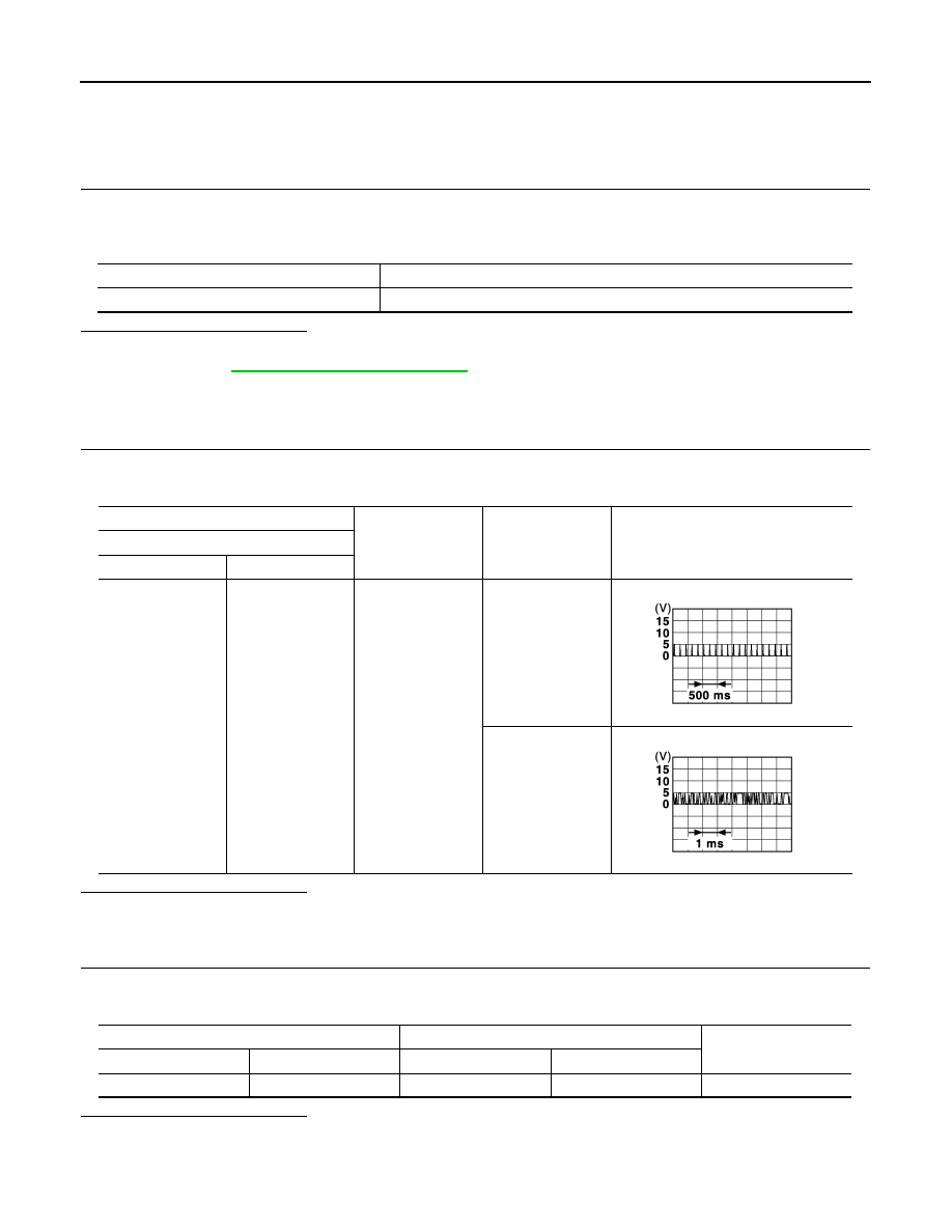
(+)
(–)
Condition
Signal
(Reference value)
Remote keyless entry receiver
Connector
Terminal
B21
2
Ground
Waiting
Signal receiving
JMKIA3838GB
JMKIA3841GB
BCM
Remote keyless entry receiver
Continuity
Connector
Terminal
Connector
Terminal
M68
20
B21
2
Existed