Infiniti QX56 (Z62). Manual - part 257


  Index      Infiniti     Infiniti QX56 (Z62) - service repair manual 2011 year


Search            


Content   ..  255  256  257  258   ..


Infiniti QX56 (Z62). Manual - part 257


DAS

PRECAUTIONS

DAS-65

< PRECAUTION >

[DCA]

C

D

E

F

G

H

I

J

K

L

M

B

N

P

A

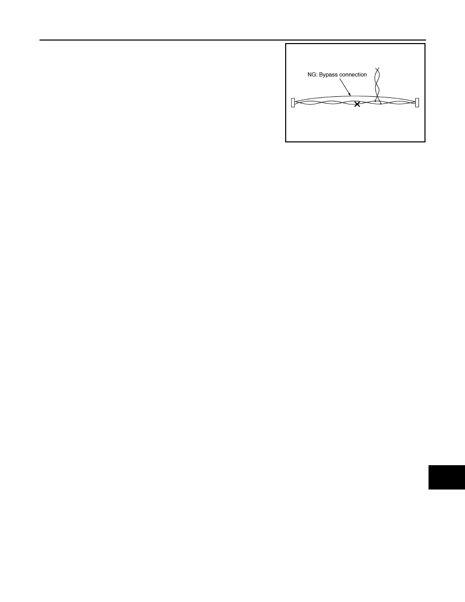
• Bypass connection is never allowed at the repaired area.

NOTE:
Bypass connection may cause ITS communication error. The
spliced wire becomes separated and the characteristics of twisted
line are lost.

DCA System Service

INFOID:0000000006223497

CAUTION:

• Never look straight into the laser beam discharger when adjusting laser beam aiming.
• Turn the MAIN switch OFF in conditions similar to driving, such as free rollers or a chassis dyna-

mometer.

• Never use the ICC sensor removed from vehicle. Never disassemble or remodel.
• Erase DTC when replacing parts of DCA system, then check the operation of DCA system after

adjusting laser beam aiming if necessary. 

SKIB8767E

DAS-66

< SYSTEM DESCRIPTION >

[DCA]

COMPONENT PARTS

SYSTEM DESCRIPTION

COMPONENT PARTS

Component Parts Location

INFOID:0000000006223498

1.

ICC steering switch

2.

Information display, ICC system 
warning lamp, buzzer
(On the combination meter)

3.

AV control unit
Refer to 

AV-9, "Component Parts Lo-

cation"

4.

Transfer control unit
Refer to 

DLN-10, "Component Parts 

Location"

5.

ICC brake hold relay

6.

ECM
Refer to 

EC-16, "Component Parts 

Location"

7.

ICC sensor

8.

TCM
Refer to 

TM-10, "A/T CONTROL 

SYSTEM : Component Parts Loca-
tion"


9.

ABS actuator and electric unit (con-
trol unit)
Refer to 

BRC-10, "Component Parts 

Location"

10. Accelerator pedal actuator

11.

Stop lamp switch

12. ICC brake switch

13. Steering angle sensor

Refer to 

BRC-10, "Component Parts 

Location"

14. ADAS control unit

Refer to 

DAS-13, "Component Parts 

Location"

A.

Back side of engine room (RH)

B.

Front bumper (center)

C.

Upper side of brake pedal

JSOIA0364ZZ

DAS

COMPONENT PARTS

DAS-67

< SYSTEM DESCRIPTION >

[DCA]

C

D

E

F

G

H

I

J

K

L

M

B

N

P

A

Component Description

INFOID:0000000006223499

Component

Description

ADAS control unit

• ADAS control unit calculates a target distance between vehicles and a target speed, 

based on signals received from each sensor and switch to transmit a brake fluid pres-
sure control signal to ABS actuator and electric unit (control unit) via CAN communica-
tion

• ADAS control unit transmits the buzzer output signal to the combination meter via CAN 

communication

• ADAS control unit transmits an accelerator pedal feedback force control signal to the 

accelerator pedal actuator via ITS communication

ICC sensor

• ICC sensor detects light reflected from a vehicle ahead by irradiating laser forward and 

calculates a distance from the vehicle ahead and a relative speed, based on the detect-
ed signal

• ICC sensor transmits the presence/absence of vehicle ahead and the distance from the 

vehicle to ADAS control unit via ITS communication

ECM

ECM transmits the accelerator pedal position signal, ICC brake switch signal, stop lamp 
switch signal, ICC steering switch signal, etc. to ADAS control unit via CAN communica-
tion

ABS actuator and electric unit (control 
unit)

• ABS actuator and electric unit (control unit) transmits the vehicle speed signal (wheel 

speed), stop lamp signal and VDC/TCS/ABS system operation condition to ADAS con-
trol unit via CAN communication

• ABS actuator and electric unit (control unit) controls the brake, based on a brake fluid 

pressure control signal received from ADAS control unit via CAN communication

TCM

TCM transmits the signal related to A/T control to ADAS control unit via CAN communi-
cation

Combination meter

Performs the following operations using the signals received from the ADAS control unit 
via the CAN communication
• Displays the DCA system operation status using the meter display signal
• Illuminates the ICC system warning lamp using the ICC warning lamp signal
• Operates the buzzer (ICC warning chime) using the buzzer output signal

Dynamic driver assistance switch
(On the ICC steering switch)

ECM receives an ICC steering switch (dynamic driver assistance switch) signal and trans-
mits the signal to ADAS control unit via CAN communication

ICC brake hold relay

ICC brake hold relay activates the stop lamp by ICC brake hold relay drive signal (stop 
lamp drive signal) outputted by the ADAS control unit

ICC brake switch

• ICC brake switch is turned OFF and stop lamp switch is turned ON, when depressing 

the brake pedal

• ICC brake switch signal is input to ECM. These signals are transmitted from ECM to 

ADAS control unit via CAN communication

• Stop lamp switch signal is input to ECM and ABS actuator and electric unit (control unit). 

These signals are transmitted from ECM and ABS actuator and electric unit (control 
unit) to ADAS control unit via CAN communication

Stop lamp switch

Transfer control unit

Transfer control unit transmits a mode selection state of 4WD shift switch to the ADAS 
control unit via CAN communication

AV control unit

AV control unit transmits the system selection signal to the ADAS control unit via CAN 
communication

Steering angle sensor

Measures the rotation amount, rotation speed, and rotation direction of steering wheel, 
and then transmits them to ADAS control unit via CAN communication

Accelerator pedal actuator

Accelerator pedal actuator receives an accelerator pedal feedback force control signal 
from the ADAS control unit via ITS communication and pushes back the accelerator pedal

DAS-68

< SYSTEM DESCRIPTION >

[DCA]

SYSTEM

SYSTEM

System Description

INFOID:0000000006223500

SYSTEM DIAGRAM

ADAS CONTROL UNIT INPUT/OUTPUT SIGNAL ITEM

Input Signal Item

JSOIA0273GB


Content   ..  255  256  257  258   ..