Infiniti QX56 (Z62). Manual - part 240
CO-20
< REMOVAL AND INSTALLATION >
WATER INLET AND THERMOSTAT ASSEMBLY
WATER INLET AND THERMOSTAT ASSEMBLY
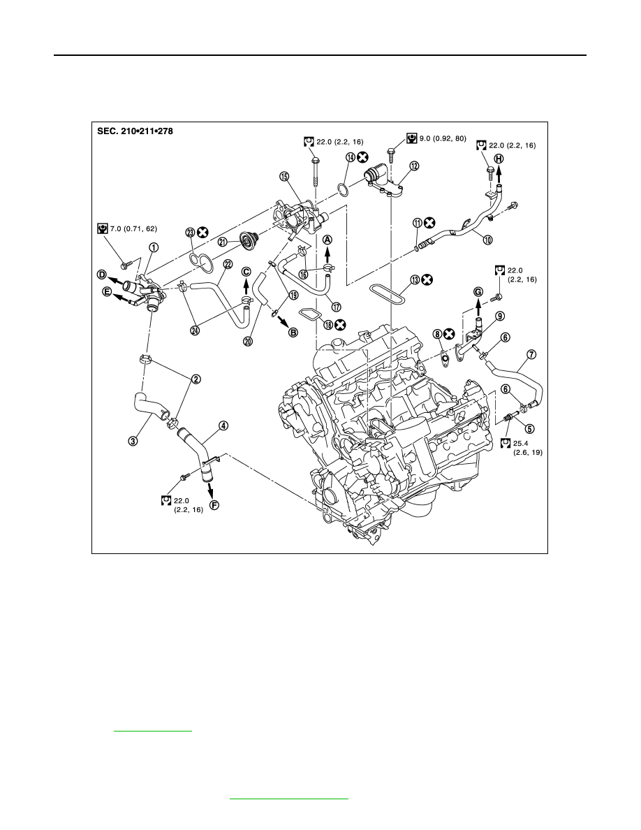
Exploded View
INFOID:0000000006289672
Removal and Installation
INFOID:0000000006289673
REMOVAL
1.
Remove engine cover. Refer to
1.
Water inlet
2.
Clamp
3.
Water suction hose
4.
Water suction pipe
5.
Hose connector
6.
Clamp
7.
Water hose
8.
Gasket
9.
Water pipe
10. Heater pipe
11.
O-ring
12.
Water connector
13. Pakkin
14. O-ring
15.
Thermostat housing
16. Clamp
17. Water hose
18.
Pakkin
19. Clamp
20. Water hose
21.
Thermostat
22. Water hose
23. Pakkin
24.
Clamp
A.
To electric throttle control actuator
B.
To oil cooler
C.
To electric throttle control actuator
D.
To radiator
E.
To reservoir tank
F.
To radiator
G
To heater
H.
To heater
Refer to
for symbols in the figure.
JPBIA3283GB