Infiniti QX56 (Z62). Manual - part 235
CHG
SERVICE DATA AND SPECIFICATIONS (SDS)
CHG-29
< SERVICE DATA AND SPECIFICATIONS (SDS)
C
D
E
F
G
H
I
J
K
L
B
A
O
P
N
SERVICE DATA AND SPECIFICATIONS (SDS)
SERVICE DATA AND SPECIFICATIONS (SDS)
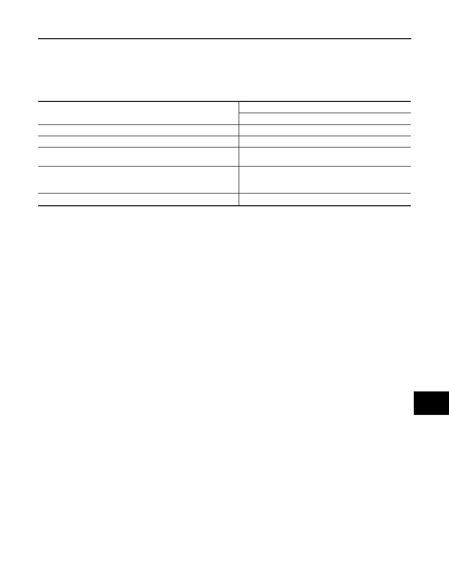
Alternator
INFOID:0000000006274881
*: Adjustment range of power generation voltage variable control is 11.4 - 15.6 V.
Type
A002TX1491
MITSUBISHI make
Nominal rating
[V - A]
12 -150
Ground polarity
Negative
Minimum revolution under no-load (When 13.5 V is ap-
plied)
[rpm]
Less than 1,300
Hot output current (When 13.5 V is applied)
[A/rpm]
More than 57/1,500
More than 126/2,500
More than 152/5,000
Regulated output voltage
[V]
14.1 - 14.7
*