Infiniti QX56 (Z62). Manual - part 138
SYSTEM
BRC-37
< SYSTEM DESCRIPTION >
[WITH VDC]
C
D
E
G
H
I
J
K
L
M
A
B
BRC
N
O
P
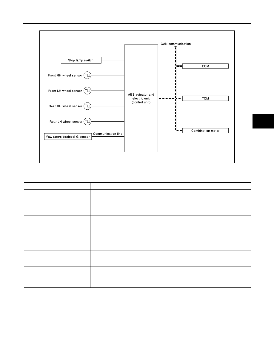
SYSTEM DIAGRAM
INPUT SIGNAL AND OUTPUT SIGNAL
Major signal transmission between each unit via communication lines is shown in the following table.
*: Communication line between yaw rate/side/decal G sensor and ABS actuator and electric unit (control unit)
BRAKE LIMITED SLIP DIFFERENTIAL (BLSD) FUNCTION
BRAKE LIMITED SLIP DIFFERENTIAL (BLSD) FUNCTION : System Description
INFOID:0000000006222577
• LH and RH driving wheel spin is always monitored. If necessary, appropriate brake force is independently
applied to LH or RH driving wheel so that one-sided wheel spin is avoided and traction is maintained. Mainly
starting ability is improved.
JPFIC0145GB
Component
Signal description
Yaw rate/side/decel G sensor
Mainly transmits the following signals to ABS actuator and electric unit (control unit) via com-
munication line *.
• Yaw rate signal
• Side G sensor signal
• Decel G sensor signal
ECM
Mainly transmits the following signals to ABS actuator and electric unit (control unit) via CAN
communication.
• Accelerator pedal position signal
• Engine speed signal
Mainly receives the following signals from ABS actuator and electric unit (control unit) via CAN
communication.
• Target throttle position signal
TCM
Mainly transmits the following signals to ABS actuator and electric unit (control unit) via CAN
communication.
• Shift position signal
Combination meter
Mainly receives the following signals from ABS actuator and electric unit (control unit) via CAN
communication.
• VDC warning lamp signal
• VDC OFF indicator lamp signal